


32
10
9
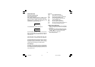
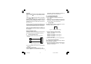
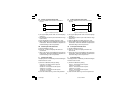
Measuring
Device
Figure 4. Measure Temperature Near Terminals
b) Wait a few minutes to allow temperature stabilization
of the entire system (compensation cable, sensor,
calibrator and instrument).
c) The displays show “rJ” and “OFF”. Using the or
button, make the readout value equal to the
temperature measured by the measuring device in
tenths of °C.
d) After a few seconds, start calibration by pushing the
FUNC button. When this calibration is complete, the
instrument will go to the next parameter.
rJ. Cold Junction Compensation Check
The displays show “rJ.” and the cold junction temperature
in tenths of °C. Make sure the display readout is equal to
the value read on the measuring device. Then, push the
FUNC button to go to the next parameter.
PL RTD Input Initial Scale Value
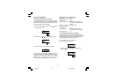
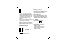
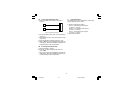
a) Connect a resistor box and the instrument as shown
in Figure 5.
10
9
8
Figure 5. Resistor Box Connection
b) Set 0.00 Ω on the resistor box.
c) Push the button; the displays show “ON” and “PL”.
d) After a few seconds, start calibration by pushing the
FUNC button. When this calibration is complete, the
instrument will go to the next parameter.
PH RTD Input Final Scale Value
a) Set resistor box to 375.00 Ω.
b) Push the button; the displays will show “ON” and
“PH”.
c) After a few seconds, start calibration by pressing the
FUNC button. When this calibration is complete, the
instrument will go to the next parameter.
P. RTD Check
The display (Figure 6) shows “P.” followed by a number
showing the measured value in counts:
P.300
00
Figure 6. RTD Calibration Check Display
a) Check the calibration (linear) by setting:
0.00 Ω – the readout must be equal to
“P.000 00” ± 10 counts;
125.000 Ω – the readout must be equal to
“P.101 90” ± 10 counts;
375.00 Ω – the readout must be equal to
“P.300 00” ± 10 counts.
b) Push the FUNC button to go to the next parameter.
7sl-6-00.p65 9/17/02, 2:44 PM32