


Performance Tests
1–90
TDS 500D, TDS 600B & TDS 700D Performance Verification and Specifications
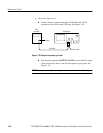
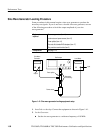
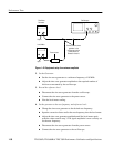
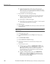
Oscilloscope
Level Meter
Power sensor
Sine Wave
Generator
Output
Input
Connect the sine wave
generator to the
oscilloscope and the
power sensor as
directed in the text.
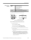
Figure 1–42: Equipment setup for maximum amplitude
2. Set the Generator:
H Set the sine wave generator to a reference frequency of 10 MHz.
H Adjust the sine wave generator amplitude to the required number of
divisions as measured by the oscilloscope.
3. Record the reference level:
H Disconnect the sine wave generator from the oscilloscope.
H Connect the sine wave generator to the power sensor.
H Note the level meter reading.
4. Set the generator to the new frequency and reference level:
H Change the sine wave generator to the desired new frequency.
H Input the correction factor and/or the new frequency into the level meter.
H Adjust the sine wave generator amplitude until the level meter again
reads the value noted in step 3. The signal amplitude is now correctly set
for the new frequency.
H Disconnect the sine wave generator from the power sensor.
H Connect the sine wave generator to the oscilloscope.