


Performance Tests
1–96
TDS 500D, TDS 600B & TDS 700D Performance Verification and Specifications
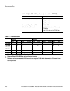
NOTE. <xxx> is the standard that you are verifying (such as OC1, OC3, OC12,
FC1063; see Table 1–12).
H From the Mask Type pop-up menu, select the mask type (<xxx>) of your
reference receiver.
H Press the Standard Mask main menu; then select your reference
receiver mask (<xxx>) from the side menu.
NOTE. For the Bessel Thompson (BT) filter to be active, the VERTICAL MENU
deskew must be set to zero on all four channels. Also, the ACQUIRE MENU
Acquisition Mode must be Sample. If you did the Factory Setup specified in
Step 1a, you selected these modes.
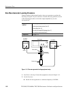
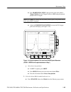
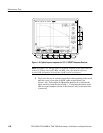
H If checking a reference receiver, verify that RR is displayed to the right
of the vertical scale factor (see Figure 1–45).
H Press TRIGGER MENU; then select Edge from the Type pop-up
menu.
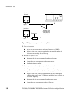
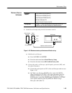
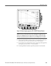
3. Turn on an FFT of the optical impulse [the Impulse Response (or Frequency
Response) of the P670xB and oscilloscope system] (Refer to Figure 1–46):
a. Press the front panel MORE button; then press the main-menu button
Math2. This turns on a math waveform.
b. If the math waveform is not set to FFT, create an FFT waveform:
H Press Change Math waveform definition; then press the main-
menu button FFT.
H Press the side-menu button Set FFT source to Ch1.
NOTE. Verify the FFT window is set to Rectangular. Also verify the FFT Vert
Scale is set to dBV RMS. If you did the Factory Setup in Step 1a, you selected
these modes.
H Press the side-menu button OK Create Math Waveform.
H Press the side menu button Average, then set the number of averages
to 16 using the general purpose knob or keypad.