


Brief Procedures
TDS 500D, TDS 600B & TDS 700D Performance Verification and Specifications
1–11
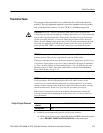
c. The horizontal POSITION knob positions the signal left and right
on-screen when rotated.
3. Remove the test hookup: Disconnect the probe from the channel input and
the probe-compensation terminals.
Equipment
required
One probe such as the P6243, P6245, P6139A, or P6339A
Prerequisites None
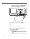
1. Install the test hookup and preset the oscilloscope controls:
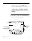
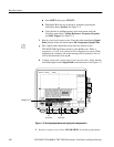
a. Hook up the signal source: Install the probe on CH 1. Connect the probe
tip to PROBE COMPENSATION SIGNAL on the front panel;
connect the probe ground to PROBE COMPENSATION GND. See
Figure 1–3 on page 1–8.
b. Initialize the oscilloscope:
H Press save/recall SETUP.
H Press the main-menu button Recall Factory Setup.
H Press the side-menu button OK Confirm Factory Init.
c. Modify default settings:
H Set the vertical SCALE to 200 mV.
H Set the horizontal SCALE for the M (main) time base to 200 ms.
H Press SET LEVEL TO 50%.
H Press TRIGGER MENU.
H Press the main-menu button Mode & Holdoff.
H Press the side-menu button Normal.
H Press CLEAR MENU to remove the menus from the screen.
2. Verify that the main trigger system operates: Confirm that the following
statements are true.
H The trigger level readout for the main trigger system changes with the
trigger-LEVEL knob.
H The trigger-LEVEL knob can trigger and untrigger the square-wave
signal as you rotate it. (Leave the signal untriggered, which is indicated
by the display not updating).
Verify the Main and
Delayed Trigger Systems