


Brief Procedures
TDS 500D, TDS 600B & TDS 700D Performance Verification and Specifications
1–7
Functional Tests
The purpose of these procedures is to confirm that the oscilloscope functions
properly. The only equipment required is one of the standard-accessory probes
and, to check the file system, a 3.5 inch, 720 K or 1.44 Mbyte floppy disk.
CAUTION. The P6217, P6243, and P6245 probes that can be used with this
oscilloscope provide an extremely low loading capacitance (<1 pF) to ensure the
best possible signal reproduction. These probes should not be used to measure
signals exceeding ±8 volts, or errors in signal measurement will be observed.
Above 40 volts, damage to the probe may result. To make measurements beyond
±10 volts, use either the P6139A probe (good to 500 volts peak), the P6339A
probe (for the TDS 794D), or refer to the catalog for a recommended probe.
STOP. These procedures verify functions; that is, they verify that the oscilloscope
features operate. They do not verify that they operate within limits.
Therefore, when the instructions in the functional tests that follow call for you to
verify that a signal appears on-screen “that is about five divisions in amplitude”
or “has a period of about six horizontal divisions,” etc., do NOT interpret the
quantities given as limits. Operation within limits is checked in Performance
Tests, which begin on page 1–15.
STOP. DO NOT make changes to the front-panel settings that are not called out
in the procedures. Each verification procedure will require you to set the
oscilloscope to certain default settings before verifying functions. If you make
changes to these settings, other than those called out in the procedure, you may
obtain invalid results. In this case, just redo the procedure from step 1.
When you are instructed to press a menu button, the button may already be
selected (its label will be highlighted). If this is the case, it is not necessary to
press the button.
Equipment
required
One probe such as the P6243, P6245, P6139A, or P6339A
Prerequisites None
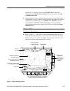
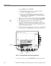
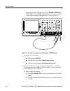
1. Install the test hookup and preset the oscilloscope controls:
a. Hook up the signal source: Install the probe on CH 1. Connect the probe
tip to PROBE COMPENSATION SIGNAL on the front panel;
Verify All Input Channels