


Performance Tests
TDS 500D, TDS 600B & TDS 700D Performance Verification and Specifications
1–45
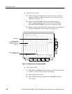
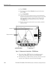
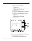
i. Use the cursors to measure the skew from CH1 to CH2, CH1 to CH3,
and CH1 to CH4 (use AX1 and AX2 instead of CH3 and CH4 if your
TDS model is so equipped). Write down these three numbers in the first
measurement column of Table 1–5. Note that these numbers may be
either positive or negative.
j. Repeat the procedure from step 1.c through 2.e.
k. Again use the cursors to measure the skew from CH1 to CH2, CH1 to
CH3, and CH1 to CH4. Write down these numbers in the second
measurement column of Table 1–5. Note that these numbers may be
either positive or negative.
l. Add the first CH1 to CH2 skew measurement to the second CH1 to CH2
skew measurement and divide the result by 2. Use Table 1–5.
m. Add the first CH1 to CH3 (AX1 on some TDS models) skew measure-
ment to the second CH1 to CH3 skew measurement and divide the result
by 2. Use Table 1–5.
n. Add the first CH1 to CH4 (AX2 on some TDS models) skew measure-
ment to the second CH1 to CH4 skew measurement and divide the result
by 2. Use Table 1–5.
o. Check against limits: CHECK that the largest of the three results from
steps l, m, and n is between –100 ps and + 100 ps for the TDS 600B or
between –50 ps and + 50 ps for the TDS 500D/700D.
p. Enter time on the test record.
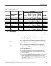
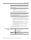
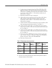
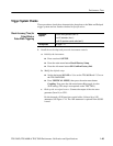
Table 1–5: Delay between channels worksheet
Coupling
First
measurement
Second
measurement
Add first and
second
measurements
Divide sum
by 2
CH1 to CH2
skew
CH1 to CH3
skew
CH1 to CH4
skew
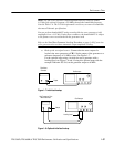
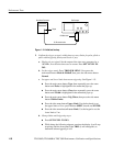
3. Disconnect the hookup: Disconnect the cable from the generator output at
the input connectors of the channels.