


Performance Tests
1–58
TDS 500D, TDS 600B & TDS 700D Performance Verification and Specifications
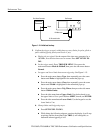
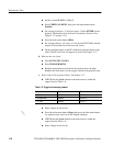
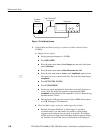
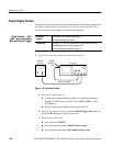
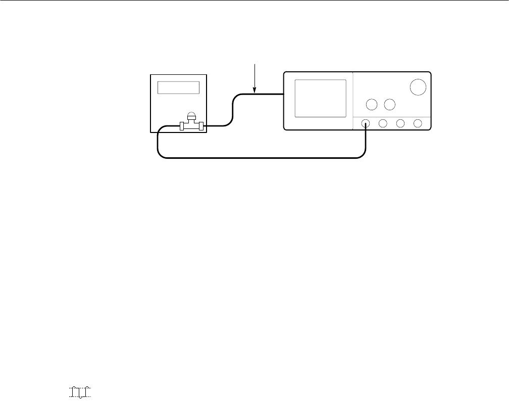
Sine Wave
Generator
Oscilloscope
To AUX TRIG INPUT
on rear panel
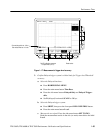
Figure 1–18: Initial test hookup
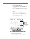
2. Confirm Main and Delayed trigger systems are within sensitivity limits
(50 MHz):
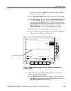
a. Display the test signal:
H Set the generator frequency to 50 MHz.
H Press MEASURE.
H Press the main-menu button Level Setup; then press the side-menu
button Min-Max.
H Press the main-menu button Select Measrmnt for Ch1.
H Press the side-menu button –more– until Amplitude appears in the
side menu (its icon is shown at the left). Press the side-menu button
Amplitude.
H Press SET LEVEL TO 50%.
H Press CLEAR MENU.
H Set the test signal amplitude for about three and a half divisions on
screen. Now fine adjust the generator output until the CH 1
Amplitude readout indicates the amplitude is 350 mV. Readout may
fluctuate around 350 mV.
H Disconnect the 50 W precision coaxial cable at CH 1 and reconnect
it to CH 1 through a 10X attenuator.
b. Check the Main trigger system for stable triggering at limits:
H Read the following definition: A stable trigger is one that is
consistent; that is, one that results in a uniform, regular display
triggered on the selected slope (positive or negative). This display
should not have its trigger point switching between opposite slopes,
nor should it roll across the screen. At horizontal scale settings of