


Operating Basics
6
TSG 601 User Manual
G Specify the peak–to–peak amplitude of the serial output, from
600 to 1000 mV (page 8).
G Choose the video components (Y, C
r
, C
b
) to be included in the
serial output (page 8).
G Specify 8- or 10-bit video sample words (page 9).
H Embed CRC information (used for “Error Detection and
Handling,” or EDH) in the output to detect or simulate errors
originating in the serial data path (page 9).
H Add an ID message to the video signal, and place it where you
want in the picture (pages 10, 11).
H Store up to eight ID messages for later use (pages 10, 16).
H Create a sequence of (up to four) stored ID messages that will
cycle continuously in the output (page 11).
H Embed Audio information in the serial video data path (page 12)
H Simulate the effect on your system of 50 m (164 ft.) of coaxial
cable (page 15).
H Detect improper termination of the serial video signal path
(page 15).
H Save all the current instrument settings as a “Preset” for later
recall (page 16).
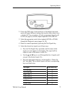
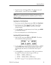
Outputting Serial Video Test Signals
1. Connect the Serial Video Output of the instrument to your
system. Use 75 Ω cable and be sure that the signal path is
terminated properly.