


Operating Basics
TSG 601 User Manual
15
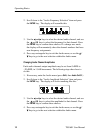
Audio Channel ID
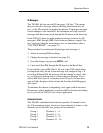
Source ID in the audio channel status bits may be enabled or dis-
abled through this menu item. Channel ID’s are preset to ch1 (chan-
nel 1), ch2 (channel 2), ch3 (channel 3), and ch4 (channel 4).
1. If necessary, enter the Audio menu (press
Shift, then Audio On/Off ).
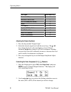
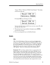
2. Scroll down to the “Audio Amplitude Selection” item and press
the
ENTER key. The display will be similar to:
3. Use the A and " keys to toggle the ID between the enabled and
disabled states. Press the
ENTER key to select the displayed state.
If the state was changed, the display will show each of the four
channels momentarily, while the SRAM is updated.
4. Press any rectangular key to exit the Audio menu, or use the
Y /
B keys to go to the next selection within the Audio menu.
Cable Simulation
H To simulate the addition of 50 meters of 75 Ω coaxial cable
anywhere in your system, connect the TSG 601 into the signal
path with the two BNCs marked “APPROX 50M CABLE.” The
connectors are interchangeable, and the circuit will accurately
simulate 50 m of Belden 8281 cable—which attenuates the signal
by approximately 5.4 dB at 135 MHz—whether the TSG 601 is
switched on or off.
Detecting Incorrect Termination
H A special
symbol will “flash” in the upper right corner of the
TSG 601 display to indicate improper termination of the serial
video signal path. The symbol is displayed whenever the instru-
ment detects return loss below approximately 10 dB, which
approximates termination impedance of less than 37.5 W or great-
er than 150 W.