


Operating Basics
20
TSG 601 User Manual
Within the audio menus, the channels are called channels 1, 2, 3, and
4 of the group that you are working in. As there must be at least two
channels (AES/EBU pairs) selected when embedded audio is en-
abled, you may select channels 1 and 2, channels 3 and 4 or channels
1, 2, 3, and 4.
Separate frequencies and amplitudes may be assigned to each of the
four channels. The frequency and amplitude assigned to a channel
will be the same for that channel in all four groups. The frequency
may be set to any of 26 provided frequencies, or mute. The ampli-
tude for each channel may be set in 1 dB increments from 0 dBFS to
–20 dBFS.
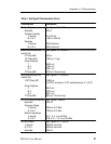
The embedded audio function also provides a source ID for each
channel. This ID is enabled or disabled for the whole group of four
channels at a time. When enabled, the source ID applies ch1, ch2,
ch3, and ch4 to the appropriate channels Status Bits, as shown in
Table 7. Audio sample distributions are shown in Tables 8 and 9.
The SDI Checkfield Signals
SDI (serial digital interface) Checkfield signals—also known as
Pathological signals—are designed to test the low frequency re-
sponse of serial digital video equipment. The three SDI Checkfield
signals in the TSG 601 are defined in the (proposed) SMPTE Recom-
mended Practice RP 178; they are the Cable Equalization (Equaliz-
er), Phase Locked Loop (PLL), and Matrix Checkfields.
The Equalizer SDI Checkfield signal tests the automatic equalizer
circuits of receiving equipment. It has been arranged to create a seri-
al data stream with the maximum possible dc content. In practice,
the digital data contains a repeating pattern of 19 high or low states
followed by one opposite state; thus, for the longest possible period
(several times each field), the signal will be essentially “dc,” with
opposite polarity states occurring only once in every twenty clock
intervals.
The PLL Checkfield Signal tests the equipment’s ability to lock to
the serial data stream. It has been configured to give the serial data
the maximum possible low frequency content and the fewest possible
zero crossings; that is, the longest possible time between high–low or
low–high transitions in the signal. In practice, the data contains—
several times each field—a repeating pattern of 20 high states fol-