


19
YORK INTERNATIONAL
FORM 160.81-EG1
The following is a user’s guide in the application and
installation of MAXE Chillers, and will ensure the reli-
ability and trouble-free life for which this equipment was
designed. While this guide is directed towards normal,
water-chilling applications, the YORK sales represen-
tatives can provide complete recommendations on other
types of applications.
Location
M
AXE Chillers are virtually vibration-free and generally
can be located at any level in a building where the con-
struction will support the total system operating weight.
The unit site must be a floor, mounting pad or founda-
tion which is level within 1/4" (6.4 mm) and capable of
supporting the operating weight of the chiller.
Sufficient clearance to permit normal service and main-
tenance work should be provided all around and above
the unit. Additional space should be provided at one
end of the unit to permit cleaning of evaporator and
condenser tubes as required. A doorway or other prop-
erly located opening may be used.
The chiller should be installed in an indoor location where
temperatures range from 40°F to 110°F (4.4°C to 43.3°C).
Water Circuits
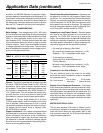
Flow Rate – For normal water chilling duty, evaporator
flow rates are permitted at water velocity levels in the heat
exchangers tubes of between 3 ft./second and 12 ft./sec-
ond (0.91 m/s and 3.66 m/s). Condenser flow rates are
permitted between 3.33 ft./sec. and 12 ft./sec. (1.01 m/s
and 3.66 m/s). Variable flow applications are possible, and
initial chiller selections should be made accordingly to
permit proper range of flow while maintaining the mini-
Application Data
mum velocity noted above. Variable flow in the condenser
is not recommended, as it generally raises the energy con-
sumption of the system by keeping the condenser pres-
sure high in the chiller. Additionally, the rate of fouling in
the condenser will increase at lower water velocities asso-
ciated with variable flow, raising system maintenance costs.
Cooling towers typically have narrow ranges of operation
with respect to flow rates, and will be more effective with
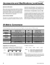
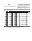
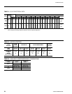
full design flow. Ref. Table 1 for flow limits.
Temperature Ranges – For normal water chilling duty,
leaving chilled water temperatures may be selected be-
tween 38°F (3.3°C) [36°F (2.2°C) with Smart Freeze en-
abled) and 70°F (21.1°C) for water temperature ranges
between 3°F and 30°F (1.7°C and 16.7°C).
Water Quality – The practical and economical application
of liquid chillers requires that the quality of the water supply
for the condenser and evaporator be analyzed by a water
treatment specialist. Water quality may affect the perfor-
mance of any chiller through corrosion, deposition of heat-
resistant scale, or sedimentation or organic growth. These
will degrade chiller performance and increase operating and
maintenance costs. Normally, performance may be main-
tained by corrective water treatment and periodic cleaning
of tubes. If water conditions exist which cannot be corrected
by proper water treatment, it may be necessary to provide a
larger allowance for fouling, and/or to specify special mate-
rials of construction.
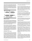
General Piping – All chilled water and condenser water
piping should be designed and installed in accordance
with accepted piping practice. Chilled water and condenser
water pumps should be located to discharge through the
chiller to assure positive pressure and flow through the
unit. Piping should include offsets to provide flexibility and
should be arranged to prevent drainage of water from the
1 383 (24.2) 1525 (96.2) 613 (38.7) 2204 (139.1)
2 192 (12.1) 762 (48.1) 307 (19.4) 1102 (69.5)
3 128 (8.1) 508 (32.1) 205 (12.9) 734 (46.3)
1 468 (29.5) 1866 (118.0) 683 (43.1) 2455 (154.9)
2 234 (14.8) 932 (58.8) 342 (21.6) 1227 (77.4)
3 157 (9.9) 621 (39.2) 228 (14.4) 818 (51.6)
1 570 (36.0) 2277 (143.7) 771 (48.7) 2774 (175.0)
2 286 (18.0) 1138 (71.8) 386 (24.4) 1386 (87.5)
3 ––– ––– ––– ––– ––– ––– ––– –––
1 693 (43.7) 2771 (174.9) 866 (54.6) 3462 (218.5)
2 346 (21.8) 1385 (87.4) 433 (27.3) 1731 (109.2)
3 231 (14.6) 924 (58.3) 289 (18.2) 1154 (72.8)
1 822 (51.9) 3287 (207.4) 1082 (68.3) 4328 (273.1)
2 411 (25.9) 1644 (103.7) 541 (34.1) 2164 (136.5)
3 274 (17.3) 1096 (69.2) 361 (22.8) 1443 (91.1)
1 986 (62.2) 3945 (248.9) 1350 (85.2) 5400 (340.1)
2 493 (31.1) 1972 (124.4) 675 (42.6) 2700 (170.0)
3 ––– ––– ––– ––– ––– ––– ––– –––
TB, VB
TC, VC
TD, VD
WB, XB
WC, XC
WD, XD
SHELL
CODE
PASS
EVAPORATOR CONDENSER
MINIMUM
MAXIMUM
MINIMUM
MAXIMUM
TABLE 1 – WATER FLOW RATE LIMITS – GPM (L/s)