


29
YORK INTERNATIONAL
FORM 160.81-EG1
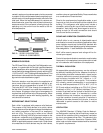
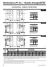
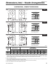
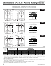
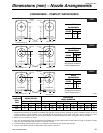
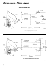
Dimensions (mm) – Nozzle Arrangements
EVAPORATORS – COMPACT WATER BOXES
1-PASS
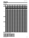
2-PASS
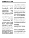
3-PASS
EVAPORATOR
EVAPORATOR EVAPORATOR
EVAPORATOR EVAPORATOR
EVAPORATOR
MOTOR END COMPRESSOR END
MOTOR END COMPRESSOR END
MOTOR END COMPRESSOR END
FLOOR LINE
FLOOR LINE
FLOOR LINE
1"
1" 1"
1"
1" 1"
GG GG
GG GG
GG GG
CC CC
DD
BB
DD
BB
DD
BB
DD
BB
AH
B
J
C
K
F
N
G
P
REAR
OF UNIT
REAR
OF UNIT
REAR
OF UNIT
REAR
OF UNIT
REAR
OF UNIT
REAR
OF UNIT
NOZZLE
ARRANGEMENTS
NO. OF EVAP.
PASSES IN OUT
1
AH
HA
NOZZLE
ARRANGEMENTS
NO. OF EVAP.
PASSES IN OUT
2
CB
KJ
NOTE: Water must enter
through bottom connection to
achieve rated performance.
NOZZLE
ARRANGEMENTS
NO. OF EVAP.
PASSES IN OUT
3
GN
PF
NOTE: Water must enter
through bottom connection to
achieve rated performance.
LD07615
NOTES:
1. Standard water nozzles are furnished as welding stub-outs with Victaulic grooves, allowing the option of welding, flanges, or use of
Victaulic couplings. Factory installed, class 150 (ANSI B16.5, round slip-on, forged carbon steel with 1/16" raised face), water flanged
nozzles are optional (add 1/2" to nozzle length). Companion flanges, nuts, bolts, and gaskets are not furnished.
2. Add 1" for isolators as shown.
3. One-, two- and three-pass nozzle arrangements are available only in pairs shown and for all shell codes. Any pair of evaporator nozzles
may be used in combination with any pair of condenser nozzles.
4. Connected piping should allow for removal of compact water boxes for tube access and cleaning.
5. Rear of unit is defined as side of chiller opposite control center.
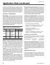
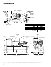
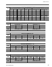
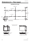
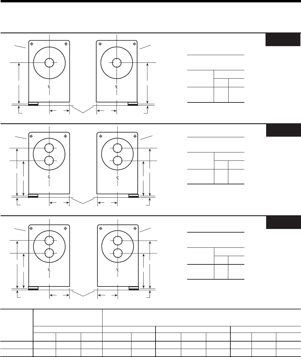
EVAPORATOR
EVAPORATOR NOZZLE PIPE SIZE
NOZZLE DIMENSIONS
SHELL
NO. OF PASSES 1-PASS 2-PASS 3-PASS
CODE
123CC
2
GG BB
2
DD
2
GG BB
2
DD GG
T, V 8" 6" 4" 578 343 330 775 343 330 775 394
W, X 10" 8" 6" 629 445 425 832 445 425 832 445