


8
YORK INTERNATIONAL
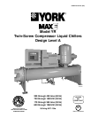
FORM 160.81-EG1
OptiView Control Center (continued)
• Slide Valve Unload (Manual)
• Slide Valve Auto
• Max. Load Temperature
• Minimum Load FLA
• Minimum Load Control Source
The HOT GAS BYPASS screen, accessed from the
COMPRESSOR screen, displays a pictorial of the by-
pass line and solenoid valve location on the chiller. The
Hot Gas ON and OFF Setpoints are programmed on
this screen and system parameters pertinent to Hot Gas
Bypass operation are displayed. An LED illuminates
when the Hot Gas solenoid is ON. If the chiller is
equipped with the Hot Gas Bypass option, operation
must be enabled on the OPERATIONS screen. From
this screen you can perform the following:
Display Only:
• Slide Valve Position
• Return Chilled Liquid Temperature
• Leaving Chilled Liquid Temperature
• Hot Gas Solenoid (LED)
Programmable:
• On Setpoint
• Off Setpoint
The SLIDE VALVE CALIBRATION screen displays a
cutaway view of the chiller compressor, revealing the
rotary screw and slide valve and provides the capabil-
ity of calibrating the slide valve. From this screen, you
can perform the following:
Display Only:
• Slide Valve Loading (LED)
• Slide Valve Unloading (LED)
• Calibration Message
Programmable:
• Start Calibration
• Cancel Calibration
The OIL SEPARATOR screen displays a close-up view
of the chiller oil separator/sump.
Display Only:
• Discharge Temperature
• Discharge Superheat
• Oil Pressure
• Discharge Pressure
• Differential Oil Pressure
• Differential Filter Pressure
• Oil Return Solenoid (LED)
• Evaporator Pressure
• Condenser Pressure
• Condenser Saturation
1. The MOTOR “soft” key on the HOME screen, when
pressed, shows a picture of either a YORK Electro-
Mechanical Starter or a Solid State Starter, depend-
ing on chiller configuration. The Programmable
pulldown demand to automatically limit motor load-
ing can be used to minimize building demand
charges. Pulldown time period control over four
hours, and verification of time remaining in pulldown
cycle from display readout. Separate digital setpoint
for current limiting between 30 and 100%.
The ELECTRO-MECHANICAL STARTER (E–M)
screen displays a picture of the starter and the follow-
ing values. The ones below are common among both
offerings and the values will be displayed on both types
of starter screens. From this screen you can perform
the following:
Display Only:
• Motor Run (LED)
• Motor Current % Full-load Amps
• Current Limit Setpoints
• Pulldown Demand Time Left
Programmable:
• Local Motor Current Limit
• Pulldown Demand Limit
• Pulldown Demand Time
The SOLID STATE STARTER (SSS) screen displays a
picture of the starter and the following values, which are
displayed in addition to the common ones listed above.
From this screen, you can perform the following:
Display Only:
• Input Power kW
• kW Hours
• Starter Model
• Voltage – Phase A, B, C
• Current – Phase A, B, C
• Temperature – Phase A, B, C