


4 - Programming Examples
128
Programming both the current and the voltage range in one program message unit can be done in any
order and will not cause an error if the final combination specifies a valid current limit for the indicated
range. If the commands
VOLTage:RANGe 300
CURRent 10;:VOLTage:RANGe 150
are sent, no error will be generated because the combined current limit and voltage range specified on the
second line are within the output ratings of the above models.
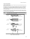
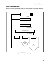
Programming Output Transients
Output transients are used to:
u Synchronize output changes with a particular phase of the voltage waveform.
u Synchronize output changes with internal or external trigger signals.
u Simulate surge, sag, and dropout conditions with precise control of duration and phase.
u Create complex, multi-level sequences of output changes.
u Create output changes that have rapid or precise timing requirements.
The following ac source functions are subject to transient control:
AC output voltage
Frequency
Phase
Waveform shape
AC voltage slew rate
Frequency slew rate
DC output voltage (Agilent 6811B/6812B/6813B only)
Peak current limit (Agilent 6811B/6812B/6813B only)
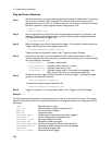
The following transient modes can be generated:
STEP
Generates a single triggered output change.
PULSe
Generates an output change which returns to its original state after some time period.
LIST
Generates a sequence of output changes, each with an associated dwell time or paced by
triggers.
FIXed
Turns off the transient functions, which means that only the IMMediate values are used as
the data source for a particular function.
NOTE: At *RST all functions are set to FIXed, which turns off the transient functions.