


Programming Examples - 4
133
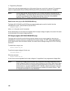
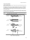
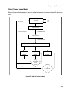
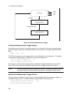
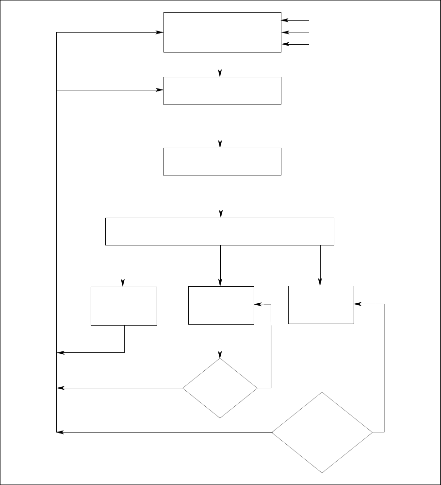
Output Trigger System Model
Figure 4-2 is a model of the output trigger system. The rectangular boxes represent states. The arrows
show the transitions between states. These are labeled with the input or event that causes the transition to
occur.
Figure 4-2. Model of Output Triggers
DELAYING STATE
STEP
INITIATED STATE
IDLE STATE
ABOR
*RCL
*RST
TRIGGER RECEIVED
DELAY COMPLETED
INIT[:IMM]
WAIT FOR SYNC STATE
INIT:CONT OFF
INIT:CONT ON
PULSE
COUNT
YES
NO
DONE?
CHANGE
PULSE
CHANGES
LIST
CHANGES
YES
NO
LIST
SYNC COMPLETED
OR
LIST:STEP ONCE
COMPLETE?
?
OR
LIST NOT COMPLETE &
LIST:STEP ONCE
OUTPUT
OUTPUT
OUTPUT