


Programming Examples - 4
129
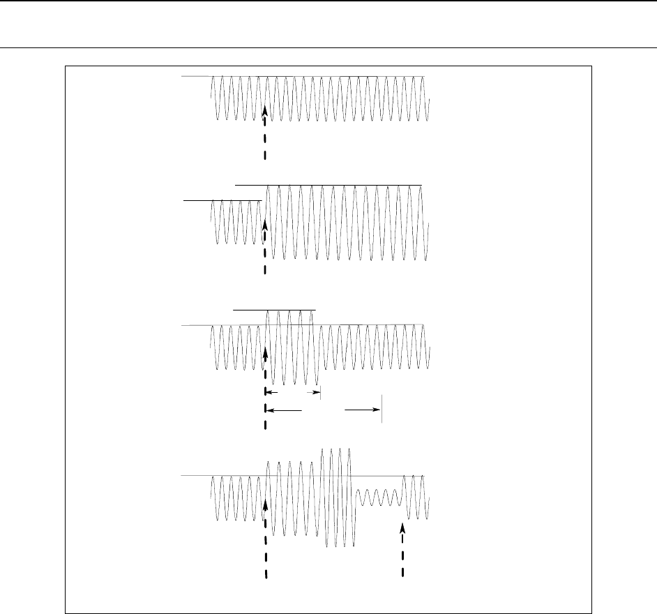
Transient System Model
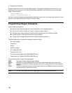
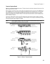
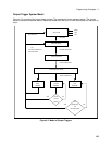
Figure 4-1 is a model of the transient system. The figure shows the transient modes and the source of the
data that generates each mode.
When a trigger is received in step or pulse modes, the triggered functions are set from their IMMediate to
their TRIGgered value. In Step mode, the triggered value becomes the immediate value. In Pulse mode,
the functions return to their immediate value during the low portion of the pulse. If there are no further
pulses, the immediate value remains in effect. In List mode, the functions return to their immediate value
at the completion of the list.
You can mix FIXed, STEP, PULSe, and LIST modes among most functions. When a trigger is received,
each function will react in a manner defined by its mode. However, this is subject to the following limitation
to ensure the proper output voltage in all cases:
NOTE: The ac voltage, waveform shape, and voltage slew functions cannot be set to Step or
Pulse mode if one of them is set to List mode.
Figure 4-1. Model of Transient System
IMMediate level
Tri
gg
er
IMMediate level
TRIGered level
IMMediate level
TRIGered level
IMMediate level
Step 0
Step 1
Applied
List
Complete
FIXED mode
STEP mode
PULSE mode
LIST mode
Tri
gg
ers i
g
nored
,
output alwa
y
s set to
immediate command levels.
At trigger, the triggered
level becomes the new
immediate level.
At trigger, the triggered
level is active during the
pulse width portion of the
At tri
gg
er
,
the list
When list completes, output
returns to immediate level.
width
period
Step 2
pulse waveform