


4 - Programming Examples
148
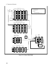
Servicing Questionable Status Events
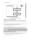
This example assumes you want a service request generated whenever the ac source’s overvoltage,
overcurrent, or overtemperature circuits have tripped. From figure 4-5, note the required path for
Questionable Status conditions at bits 0, 1, and 4 to generate a service request (RQS) at the Status Byte
register. The required register programming is as follows:
Step 1
Program the Questionable Status PTR register to allow a positive transition at bits 0, 1, or
4 to be latched into the Status Event register. Use:
STATus:QUEStionable:PTR 19 (1 + 2 + 16 = 19)
Step 2
Program the Questionable Status Enable register to allow the latched events to be
summed into the QUES summary bit. Use:
STATus:QUEStionable:ENABle 19
Step 3
Program the Service Request Enable register to allow the QUES summary bit from the
Status Byte register to generate RQS. Use:
*SRE 8
Step 4
When you service the request, read the event register to determine which Questionable
Status Event register bits are set and clear the register for the next event. Use:
STATus:QUEStionable:EVENt?
Monitoring Both Phases of a Status Transition
You can monitor a status signal for both its positive and negative transitions. For example, to generate
RQS when the ac source either enters the CLrms (rms current limit) condition or leaves that condition,
program the Questionable Status PTR/NTR filter as follows:
STATus:QUEStionable:PTR 4096;NTR 4096
STATus:QUEStionable:ENABle 4096;*SRE 8
The PTR filter will cause the QUES summary bit to set RQS when CLrms occurs. When the controller
subsequently reads the event register with STATus:QUEStionable:EVEN?, the register is cleared. When
CLrms subsequently goes false, the NTR filter causes the QUES summary bit to again set RQS.
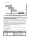
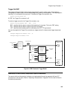
Programming the Trigger In and Trigger Out BNC Connectors
The ac source has two bnc connectors labeled Trigger In and Trigger Out (see figure 4-6). Refer to
"Operating Characteristics" in appendix A of the User’s Guide for the electrical parameters.
Trigger In BNC
This chassis-referenced digital input can be selected as a source for transient or measurement triggers.
This allows an action to be synchronized to an external signal. The trigger is recognized on a high-to-low
transition of the input signal. The minimum pulse width of the signal is 1 microsecond. To select the
Trigger In connector as the trigger source, use:
TRIGger:SEQuence1:SOURce EXTernal or
TRIGger:TRANsient:SOURce EXTernal
TRIGger:SEQuence3:SOURce EXTernal or
TRIGger:ACQuire:SOURce EXTernal