


Programming Examples - 4
149
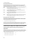
Trigger Out BNC
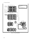
This chassis-referenced digital output can be programmed to supply a pulse output at the leading or
trailing edge of a step or pulse, or at the leading edge of any point in a list sequence. The output signal is
nominally a 10 microsecond low-true pulse. To enable the Trigger Out connector, use:
OUTPut:TTLTrg:STATe ON
At *RST, the Trigger Out connector is off.
To select a trigger source for the Trigger Out connector, use:
OUTPut:TTLTrg:SOURce BOT | EOT | LIST
BOT - specifies that the pulse is output at the beginning of a transient. This is the *RST setting.
EOT - specifies that the pulse is output at the end of a transient.
LIST - specifies that the pulse position is defined by the LIST:TTLTrg command.
You can also specify the Trigger Out connector as a trigger source for measurement trigger sequences.
Use:
TRIGger:SEQuence3:SOURce TTLT or
TRIGger:ACQuire:SOURce TTLT
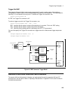
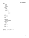
Figure 4-6. BNC Connector Trigger Model
Remote Inhibit and Discrete Fault Indicator
The remote inhibit and discrete fault indicators are implemented through the respective INH and FLT
connections on the rear panel. Refer to "Operating Characteristics" in appendix A of the User’s Guide for
the electrical parameters.
TRIGGER
SOURCE
TRIGGER OUT
OUTP:TTLT:SOUR
TRIGGER IN
TRIGGER
SYSTEM
BUS
EXT
TRIG:ACQ:SOUR
TTLT
BOT
EOT
OUTPUT
LIST
TRIG:TRAN:SOUR
IMM
TRANSIENT
TRIGGER
TRIGGER
SYSTEM
MEASUREMENT
ACQUISITION
TRIGGER
EXT
OUTP:TTLT:STAT
ON
OFF
BUS