


Programming Examples - 4
141
To select GPIB bus triggers (group execute trigger, device trigger, or *TRG command), use:
TRIGger:SEQuence3:SOURce BUS or
TRIGger:ACQuire:SOURce BUS
To select the signal driving the Trigger Out BNC connector, use:
TRIGger:SEQuence3:SOURce TTLTrg or
TRIGger:ACQuire:SOURce TTLTrg
Generating Measurement Triggers
Providing that you have specified the appropriate trigger source, you can generate triggers as follows:
u By sending one of the following over the GPIB:
TRIGger:SEQuence3:IMMediate
TRIGger:ACQuire:IMMediate
*TRG
a group execute trigger
u By applying a signal with a high-to-low transition to the Trig In BNC connector.
u By generating an output transient that causes the Trig Out BNC connector to output a pulse.
u By pressing the front panel Trigger key when the unit is operating in local mode.
Controlling the Instantaneous Voltage and Current Data Buffers
Varying the Voltage and Current Sampling Rate
At *RST, the output voltage and current sampling rate is 40kHz (period = 25
µ
s). This means that it takes
about 100 milliseconds to fill up 4096 data points in the voltage and current data buffers with the
information required to make a measurement calculation. You can vary this data sampling rate with:
SENSe:SWEep:TINTerval <sample period>
The sample period can be programmed from a minimum period of 25 microseconds (the default), to 250
microseconds in 25 microsecond steps.
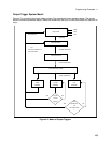
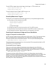
Pre-event and Post-event Triggering
The ac source continuously samples the instantaneous output voltage and current. While this is
happening, you can move the block of data that is being read into the voltage and current buffers with
respect to the data acquisition trigger. This permits pre-event or post-event data sampling. To offset the
starting point of the data buffer relative to the acquisition trigger, use:
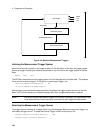
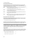
SENSe:SWEep:OFFSet:POINts <offset>
The range for this offset is 4096 to 2E9 points. As shown in the following figure, when the offset is
negative, the values at the beginning of the data record represent samples taken prior to the trigger. When
the value is 0, all of the values are taken after the trigger. Values greater than zero can be used to
program a delay time from the receipt of the trigger until the data points that are entered into the buffer are
valid. (Delay time = Offset X Sample period).