


28.
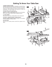
FIG. 8
4
5
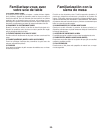
FIG. 9
7
9
9
10
8
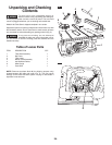
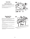
ATTACHING THE GUARD ASSEMBLY
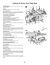
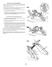
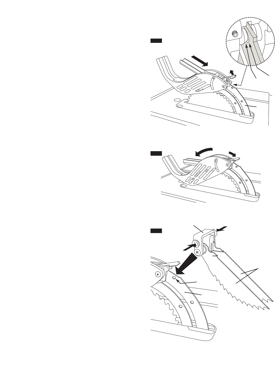
8. With one hand, hold the front of the barrier guard assembly 4
by the metal “fork”. With the other hand, hold the guard
release lever
5 up (Fig. 7).
9. Lower the rear of guard assembly and slip the cross bar
6 into
the rear notch
7 on top of the riving knife 2 (Fig. 7).
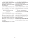
10. Lower the front of the guard assembly
4 until the metal “fork”
is parallel with the table (Fig. 8).
11. Press down on the guard release lever 5 until you feel and
hear it snap into the locking position. Check that the guard
assembly is securely connected (Fig. 8).
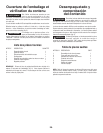
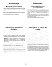
ATTACHING THE ANTI-KICKBACK DEVICE
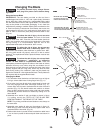
12. Attach the Anti-Kickback Device 7 into the flat recessed
area
8 of the riving knife 2 (Fig. 9).
13. Squeeze the compression pads
9 while nesting the device
into the flat area (Fig. 9).
14. Release the compression pads such that the Anti-Kickback
Device locks onto the riving knife immediately behind the
guard assembly. Check that the attachment pin is securely
connected into locking hole. Carefully raise and lower the
pawls
10 – when letting go, the spring-loaded pawls must
come down and contact the table insert (Fig. 9).
Hint: Position the Anti-Kickback Device behind the flat recessed
area and slide it towards the front until it drops into the recessed
area – then release the compression pins.
Note: The two attachments are independant of each other, so
the Anti-Kickback Device can be attached before the Guard
Assembly.
FIG. 7
4
5
7
6
2
2