


56.
Setting Fence with Digital Carriage
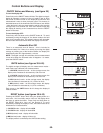
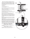
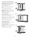
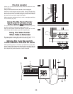
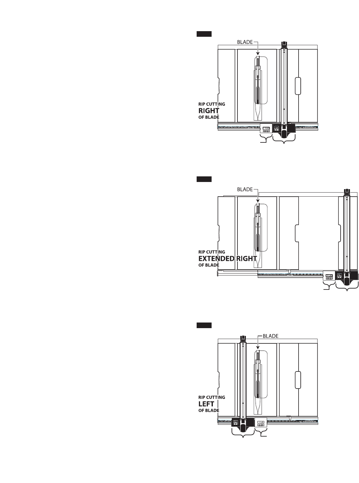
Right Side Rip Cuts 0” to 13-1/2” (fig. 43)
C
onnect fence to the right side of the digital carriage. If
necessary, follow “Zero Out” instructions above.
1
) Pull up to release the fence lock handle.
2) Move fence away from blade.
3) Stop movement when the desired setting is displayed on the
c
arriage.
4) Push down fence lock handle before starting cut.
Follow normal rip cut procedures – see page 74.
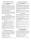
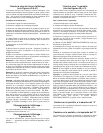
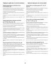
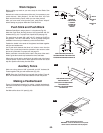
Extended Right Side Rip Cuts 13-1/2” to 25”
(fig. 44)
Connect fence to the right side of digital carriage. If necessary,
follow “Zero Out” instructions above.
1) Pull up to release the fence lock handle.
2) Move fence away from blade.
3) Stop movement when the fence contacts the front rail right
stop plate (at around 13-1/2 inches).
4) Push down fence lock handle before starting cut.
5) Lift saw’s table extension lock handle (under front rail) to
unlock.
6) Continue to move locked fence and extension table to the
right until the desired setting is displayed on the carriage
(maximum is 25”).
7) Press down on table extension lock handle to lock.
Follow normal rip cut procedures – see page 74.
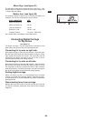
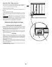
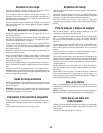
Left Side Rip Cuts (fig. 45)
Connect fence to the left side of the digital carriage. If necessary,
follow “Zero Out” instructions above.
1) Pull up to release the fence lock handle.
2) Move fence away from blade.
3) Stop movement when the desired setting is displayed on the
carriage – movement to the left of “0” will cause the “-“ (minus
sign) to appear.
4) Push down fence lock handle before starting cut.
Follow normal rip cut procedures – see page 74.
DIGITAL CARRIAGE
FENCE
DIGITAL CARRIAGE
FENCE
DIGITAL CARRIAGE
FENCE
FIG. 43
FIG. 44
FIG. 45