


42.
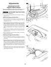
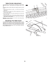
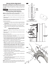
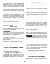
Riving Knife Alignment
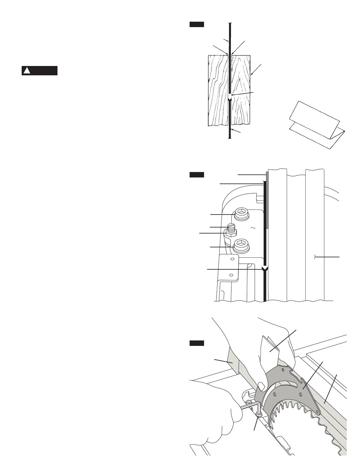
IMPORTANT: The Riving Knife 1 must always be in line with the
Saw Blade
2. The Riving Knife 1 is thinner than the width of the Kerf
4 b
y approximately three thicknesses of paper
5 o
n each side (Fig
27).
Note: The Kerf is the width of the cut made by the teeth on the
saw blade.
To prevent personal injury, always disconnect plug
from power source before making any adjustments
and when attaching or removing the Smart Guard System.
Checking Riving Knife Alignment
NOTE: The Riving Knife has been properly aligned at the factory -
Check the alignment before making any adjustments.
1. Raise the Saw Blade to maximum height and set the bevel angle
to 0°.
2. Remove the Barrier Guard Assembly and Anti-Kickback Device
(see manual).
3. Place the Rip Fence
3 on the right side and slide it until it
touches the tips of the Saw Blade 2 - Lock fence.
4. Check the alignment:
A. From the top, look down over the Fence and check that the
Riving Knife is in line (front to back) with the blade and parallel
with the fence.
B. Slide the fence away from the blade. Look over the front of the
blade and check that the Riving Knife is in line with the blade.
C. If steps A or B show misalignment, proceed to “Adjusting Riving
Knife”.
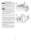
Adjusting Riving Knife
1. Raise the Saw Blade 2 to maximum height and set the bevel
angle to 0°.
2. Remove the Barrier Guard Assembly and Anti-Kickback Device
(see manual).
3. Remove the Table Insert.
4. Place the Rip Fence
3 on the right side and slide it until it touches
the tips of the Saw Blade 2 - Lock fence.
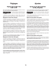
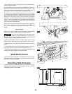
5. Loosen Hex Nut
6 with 10mm open end wrench (Fig. 28). Slightly
loosen Clamping Screws 8 (1/4-1/2 turns) using a 5mm Allen
wrench provided with table saw (stored in right side of base).
Loosen Set Screw
7 using a flat screwdriver (Fig. 28).
6. Make two folds in a small piece of paper (6" x 6") forming three
layers (Fig. 27). Paper 5 is used as a “Spacing Gauge”.
NOTE: The spacing instructions above are based on using a
standard kerf blade (.128” kerf on the Bosch blade included). If a
smaller kerf blade is used, adjust the paper spacer. For instance,
if the kerf of the replacement blade is near .100”, use 1 thickness
of paper as a spacer; if the kerf is near .110”, use 2 thicknesses.
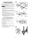
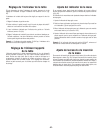
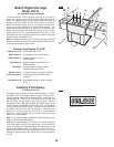
7. Insert folded paper
5 between Riving Knife 1 and Fence 3.
A.
Hold Riving Knife and paper firmly against Fence (Fig. 28 & 29).
B. Lightly tighten the clamp screws
8.
C. Remove the paper - Slide fence away from blade.
D. Slowly turn the Set Screw
7 while watching the Riving Knife tilt
until it is in line with the blade.
E. Recheck squareness of riving knife to table by sliding fence
against blade. Readjust if necessary.
8. After completing adjustments:
A. Lightly tighten hex nut
6 (hold set screw position with
screwdriver while tightening nut).
B. Fully tighten Clamp Screws
8 with Allen wrench. Then fully
tighten the hex nut.
NOTE: Check that the riving knife stays in line with blade when the
blade is tilted at any angle. Replace the Barrier Guard Assembly and
Anti-Kickback Device before making cuts.
WARNING
!
5
5
4
2
1
5
FIG. 27
WORK
BOIS
MADERA
LOOKING DOWN ON SAW
VUE DE DESSUS
VISTA HACIA ABAJO SOBRE LA SIERRA
7
6
8
8
1
2
FIG. 28
5
3
3
3
1
5
8
FIG. 29