


Chapter 1 Overview
Back Panel Ports and LEDs
1-4
Cisco 815 Integrated Services Router Hardware Installation Guide
OL-9558-01
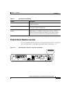
Back Panel Ports and LEDs
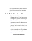
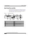
This section describes the router back panel ports and LEDs, which are shown and
identified in Figure 1-3 and are described in Table 1-2 and Table 1-3. Figure 1-4
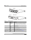
shows a closer view of the WIC-4ESW module, which is installed in the WIC 0
slot on the router. Figure 1-5 shows a closer view of the HWIC-CABLE-D-2
module, which is installed in the WIC 1 slot on the router.
Figure 1-3 Back Panel Ports and LEDs
1
Kensington-compatible locking socket
7
WIC 1 OK LED
2
WIC 0 slot
8
Module OK LED
3
Console port
9
Auxiliary port
4
WIC 1 slot 10 10/100-Mbps Fast Ethernet port
5
Power switch
11
Full duplex (FDX), 100, Link LEDs
6
Power socket
12
WIC 0 OK LED
+5, +12, -12 VDC
CONSOLE
10/100 ETHERNET
AUX
FDX LINK100WIC 0 OK WIC 1 OKMOD OK
Cisco 815
146791
LINK
US
ONLINE
HWIC-CABLE-D-2
POWER
DS
CABLE
1
2
3
4
5
6
7
8
9
10
11
12
1x
ACT LNK
2x
ACT LNK
3x
ACT LNK
4xACT
LNK
WIC
4ESW