


C-3
Cisco 815 Integrated Services Router Hardware Installation Guide
OL-9558-01
Appendix C Installing and Upgrading Memory and Virtual Private Network Modules
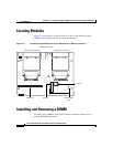
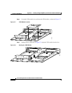
Opening the Chassis
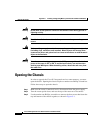
Figure C-1 Removing the Chassis Screws
Step 4
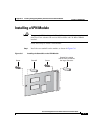
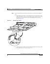
Holding the router assembly together, turn the router back to its original position.
Step 5 Gently remove the top of the router (which is facing up toward you) up and away
from the bottom of the router (which is resting on the flat surface).
At this point, you might have to disconnect the fan, which is inside the top of the
router chassis, from the motherboard, by disconnecting the fan cable from the
connector (labeled FAN) on the motherboard.
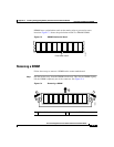
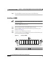
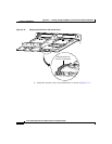
Step 6 Place the router bottom on an antistatic mat, and begin installing memory.
#1 Phillips screwdriver
155191
CONSOLE
AUX
FDX
WIC0OK
LINK
100
WIC1OK
MODOK
10/100 E
TH
E
R
N
E
T
+5, +12, -12 VDC
1
x
A
C
T
LN
K
2
x
A
C
T
L
N
K
3
x
A
C
TLN
K
4xA
C
T
LN
K
W
IC
4ESW
LIN
K
US
O
N
LIN
E
H
W
IC
-C
A
B
L
E
-D
-2
PO
W
ER
D
S
C
ABLE
Cisco 815