


1-3
Cisco ASR 901 10G Series Aggregation Services Router Hardware Installation Guide
OL-28105-02
Chapter 1 Introduction
Hardware Description
–
T1/E1 ports
–
Ethernet ports
–
SFP ports
–
Chassis: Single LED for multiple conditions
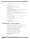
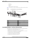
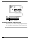
Figure 1-1 shows the front view of the Cisco ASR 901 10G router (TDM version) with each interface
module.
Figure 1-1 Cisco ASR 90110G Router—Front View of TDM Version
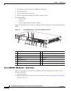
Cisco ASR 901 10G Router—Front View of Ethernet Version
The front panel of the Cisco ASR 901 10G (Ethernet version) router has the following components:
• Two SFP+ connectors for optical 10G ports (positions 0 and 1)
• Eight SFP connectors for optical GE ports (positions 4, 5, 6, 7, 8, 9, 10, and 11)
• Eight RJ-45 connectors for copper Ethernet ports, labeled “GE” (positions 0, 1, 2, 3, 4, 5, 6, and 7)
• A single RJ-45 connector for management port, labeled “MGMT”
• A single RJ-45 connector for console, labeled “CONSOLE”
• A single RJ-45 jack for the BITS interface, labeled “BITS”
• A single RJ-45 jack for the ToD interface, labeled “ToD”
7
11
5
13
12
8
6
10
9
4
3
2
14
1
334524
1 Power LED 8 BITS port
2 10G SFP+ 9 MINI-coax connector (10MHZ)
3 8 SFP ports 10 MINI-coax connector (1PPS)
4 8 GE port 11 USB port
5 Management port 12 Alarm
6 Console port 13 8 T1/E1 ports
7 ToD port 14 Power connector (DC or AC)