


3-22
Cisco ASR 901 10G Series Aggregation Services Router Hardware Installation Guide
OL-28105-02
Chapter 3 Installing the Cisco ASR 901 10G Router
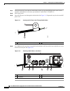
Connecting Cables
Step 1 Ensure the router is powered off.
Step 2 Connect one end of the cable to the T1 or E1 (RJ-48C) port. Use a T1/E1 cable.
Step 3 Connect the other end to the BTS patch or demarcation panel at your site.
Step 4 Turn on power to the router (see “Powering on the Router” section on page 3-24 for more details).
For more information about T1/E1 connectors including pinouts, see “T1/E1 Port Pinouts” section on
page B-2.
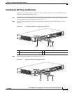
Connecting SFP Cables
Complete these steps to connect the cable to a router SFP port.
Step 1 Ensure the router is powered off.
Step 2 Insert the SFP module patch cable into the slot until you feel the connector on the cable snap into place
in the rear of the slot.
Step 3 Connect the other end to the patch or demarcation panel at your site.
Step 4 Turn on power to the router (see “Powering on the Router” section on page 3-24 for more details).
For more information about SFP connectors, see “SFP and SFP+ Port Pinouts and Cable Specifications”
section on page B-2.
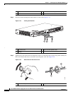
Connecting Cables to the BITS Interface
Complete these steps to connect the cable to the router BITS port:
Step 1 Ensure the router is powered off.
Step 2 Connect one end of the cable to the BITS port using a T1/E1 cable.
Step 3 Connect the other end to the SETS unit.
Step 4 Turn on power to the router (see “Powering on the Router” section on page 3-24 for more details).
For more information about T1/E1 connectors including pinouts, see “BITS Port Pinouts” section on
page B-6.
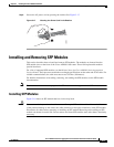
Connecting GPS Cables
The following sections describe how to connect cables from the Cisco ASR 901 10G router to a GPS
unit for input or output timing or frequency.
• Connecting Cables to the 10Mhz or 1PPS Interface
• Connecting Cables to the ToD Interface