


3-2
Cisco ASR 901 10G Series Aggregation Services Router Hardware Installation Guide
OL-28105-02
Chapter 3 Installing the Cisco ASR 901 10G Router
Mounting the Cisco ASR 901 10G Router
Mounting the Cisco ASR 901 10G Router
Note The Cisco ASR 901 10G router is qualified only for horizontal orientation. You should use additional
safety measures for vertical orientation.
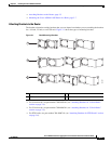
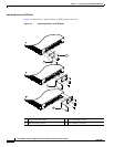
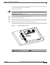
Each Cisco ASR 901 10G router includes rack-mounting brackets. Using the rack-mounting brackets,
you can mount the Cisco ASR 901 10G router in a 19-inch, 23-inch, or an ETSI rack that conforms to
the EIA-310-D specification.
Using the two rack-mounting brackets for mounting, you can recess Cisco ASR 901 10G router in the
equipment rack. This arrangement provides extra space in front of the router for the cables and allows
you to close the doors of racks equipped with front-close doors.
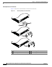
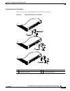
To attach or replace the rack-mounting brackets, see the “Attaching Brackets to the Router” section on
page 3-3.
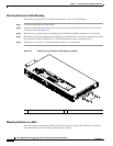
The rack-mounting brackets are slotted to allow the router to be mounted in racks with EIA 1.25-inch
(3.175-cm) or WECO 1.0-inch (2.54-cm) hole spacing. When installed in the rack, the
Cisco ASR 901 10G router requires one EIA 1.75-inch (4.4-cm) vertical mounting space (or 1 rack unit
[RU]) for mounting (see the “Mounting the Cisco ASR 901 10G Router in a Rack” section on page 3-7).
Caution Allow clearance on either side of the router for cooling air to be drawn in through the right side and
circulated through the chassis and out the three-fan exhaust ports mounted on the other side of chassis.
Rack-Mounting Configuration Guidelines
Follow these guidelines to configure the equipment rack:
• When mounting the router to an equipment rack, ensure that the rack is bolted to the floor.
• Because you may install more than one router into the rack, ensure that the weight of all of the
routers installed does not make the rack unstable.
Caution Some equipment racks are also secured to ceiling brackets, if necessary, due to the weight of the
equipment in the rack. Make sure that the rack you use to install the routers is secured to the building
structure.
• As mentioned in the “Air Flow Guidelines” section on page 2-5, maintain a 6-inch (15.24-cm)
clearance on each side of the router to ensure adequate air intake and exhaust.
• Avoid installing the routers in an overly congested rack. Air flowing to or from other routers in the
rack might interfere with the normal flow of cooling air through the routers, increasing the potential
for overtemperature conditions within the routers.
• Allow at least 19 inches (48.7 cm) of clearance at the front and rear of the rack for router
maintenance.
• Follow your local practices for cable management. Ensure that cables to and from the routers do not
impede access to perform equipment maintenance or upgrades.
To install the switch in a 19-inch, 23-inch, or a European Telecommunications Standards Institute (ETSI)
rack, follow these instructions (The ETSI racks require optional mounting hardware):