


3-23
Cisco ASR 901 10G Series Aggregation Services Router Hardware Installation Guide
OL-28105-02
Chapter 3 Installing the Cisco ASR 901 10G Router
Connecting Cables
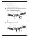
Connecting Cables to the 10Mhz or 1PPS Interface
Complete these steps to connect cables to the 10Mhz or 1PPS interface:
Step 1 Ensure the router is powered off.
Step 2 Connect one end of a mini-coax cable to the GPS unit.
Step 3 Connect the other end of the mini-coax cable to the 10Mhz or 1PPS port on the Cisco ASR 901 10G
router.
For instructions on how to configure clocking, see the Cisco ASR 901 Series Aggregation Services
Router Software Configuration Guide.
For more information about 10Mhz and 1PPS port pinouts, see “GPS Port Pinouts” section on page B-7.
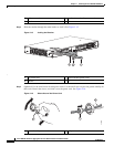
Connecting Cables to the ToD Interface
Complete these steps to connect cables to the ToD interface for GPS timing.
Step 1 Ensure the router is powered off.
Step 2 Connect one end of a straight-through Ethernet cable to the GPS unit.
Step 3 Connect the other end of the cable to the ToD port on the Cisco ASR 901 10G router.
For instructions on how to configure clocking, see the Cisco ASR 901 Series Aggregation Services
Router Software Configuration Guide.
Note For more information about BITS port pinouts, see “Time of Day Pinouts” section on page B-6.
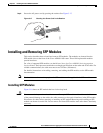
Connecting to Alarm Port
Use a straight cable to connect to the alarm port. For details on the pinouts, see “Alarm Port Pinouts”
section on page B-8.
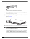
Connecting to the Management Ethernet Port
Use a straight or a cross over ethernet cable to connect to the management ethernet port. For details on
the pinouts, see “Management Ethernet Port Pinouts” section on page B-9.
Dressing Router Cables
Ensure all Cisco router cables are properly insulated so as not to interfere with each other or other pieces
of equipment. Use local practices to ensure that the cables attached to your router are properly insulated.