


3-11
Cisco ASR 901 10G Series Aggregation Services Router Hardware Installation Guide
OL-28105-02
Chapter 3 Installing the Cisco ASR 901 10G Router
Mounting the Cisco ASR 901 10G Router
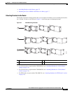
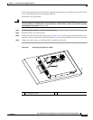
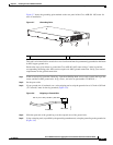
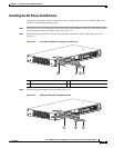
Figure 3-7 shows the grounding point marked on the rear panel of the Cisco ASR 901 10G router for
ease of installation
Figure 3-7 Grounding Point
This unit is to be installed in a restrictive access location and must be permanently grounded to minimum
6-AWG copper ground wire.
Perform the steps given below to ground the Cisco ASR 901 10G router using a 2-hole lug and the
corresponding mounting point. Most carriers require a 6-AWG ground connection. Verify your carrier’s
requirements for the ground connection.
Step 1 In the accessory kit, locate the 2-hole lug, 2 pan-head Phillips head screws used to attach the lug to the
router, and the 6-AWG ground wire. (Lug, screws, and wire are part number 32-0629-01.)
Step 2 Set the parts aside.
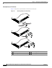
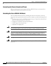
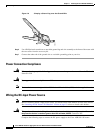
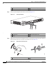
Step 3 If your ground wire is insulated, use a wire-stripping tool to strip the ground wire to 0.5 inch ± 0.02 inch
(12.7 mm ±0.5 mm) for the ring terminal (Figure 3-8).
Figure 3-8 Stripping a Ground Wire
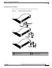
Step 4 Slide the open end of the ground lug over the exposed area of the ground wire.
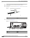
Step 5 Using a crimping tool (as specified by the ground lug manufacturer), crimp the ground lug to the ground wire
(Figure 3-9).
2
1
334636
1 Fan 2 Grounding point lug
Insulation
Wire lead
0.5 in. (12.7 mm)
±
0.02 in. (0.5 mm)
60528