


B-2
Cisco ASR 901 10G Series Aggregation Services Router Hardware Installation Guide
OL-28105-02
Appendix B Cable Specifications
SFP and SFP+ Port Pinouts and Cable Specifications
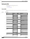
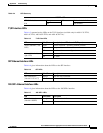
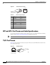
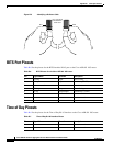
Figure B-1 RJ-45 Connector and Port
SFP and SFP+ Port Pinouts and Cable Specifications
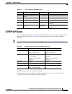
For information about SFP and SFP+ modules supported by the Cisco ASR 901 10G router, including
pinouts, see the Connector and Cable Specifications document on Cisco.com.
Note Pins not listed in the tables in this appendix are not connected.
T1/E1 Port Pinouts
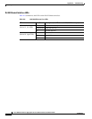
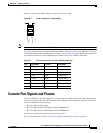
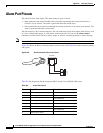
Figure B-2 shows the RJ-48C connector used by the T1/E1 ports on the TDM interface module on the
Cisco ASR 901 10G router.
Figure B-2 RJ-48C Connector
Table B-1 RJ-45 Connector Pinouts
Pin FE Signal GE Signal
1 TX data+ TX A+
2 TX data– TX A–
3RX data+ RX B+
4 Not used TX C+
5 Not used TX C–
6RX data– RX B–
7 Not used RX D+
8 Not used RX D–
205053
12345678
24939
8 7 6 5 4 3 2 1
RJ-48C connector