


B-8
Cisco ASR 901 10G Series Aggregation Services Router Hardware Installation Guide
OL-28105-02
Appendix B Cable Specifications
Alarm Port Pinouts
Alarm Port Pinouts
The router has four alarm inputs. The alarm setting is open or closed.
• Open means that the normal condition has current flowing through the contact (referred to as
normally closed contact). The alarm is generated when the current stops.
• Closed means that no current flows through the contact (referred to as normally open contact). The
alarm is generated when the current flows.
The alarm input is a dry-contact alarm port. You can connect up to four alarm inputs from devices, such
as a door, a temperature gauge, or a fire alarm, to the alarm port. You can use the alarm-contact
command to set the alarm severity to minor, major, or critical. An alarm generates a system message.
Note External DC bias is not required for the alarm port inputs.
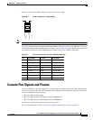
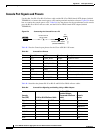
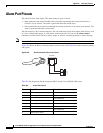
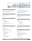
Figure B-6 shows the RJ-45 connector pinouts used for alarm, and Table B-9 lists the connector pinouts
and signals.
Figure B-6 RJ-45 Connector Pinouts for Alarm
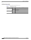
Table B-9 list the pinouts for the alarm port (RJ45) on the Cisco ASR 901 10G router.
353579
12345678
Table B-9 Alarm Port Pinout
Pin Signal Name Description
1 Alarm input 1
2 Alarm input 2
3 Not connected
4 Alarm input 3
5 Alarm input 4
6 Not connected
7 Not connected
8 Alarm input return