


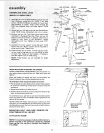
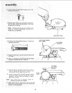
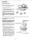
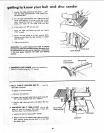

INSTALLING WORK TABLE
NOTE: Apply coat of paste wax ;o the work table.
This will make it alittle easier to feed the work.
1. Loosen the table positioning screw.
2. Insert the table support rod in the hole in the base
until the edge of the table is approximately 1/16"
from the abrasive disc, Tighten the screw.
NOTE: There is asecond mounting hole in the base. This
is for mounting the table when the belt is used in a ver-
tical position.
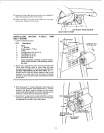
WARNING: To avoid trapping the work or fingers be-
tween the table and sanding surface, the table edge
should be a maximum 1/16 inch from the sanding
surface, the table should be completely engaged on
the rod.
/
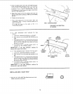
SECOND
MOUNTING
HOLE TABLE
POSITIONING
SCREW
\
TABLE
SUPPORT
ROD
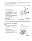
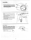
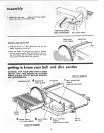
INSTALLING ABRASIVE BELT-TENSIONING
AND TRACKING
WARNING: FOR YOUR OWN SAFETY, TURN
SWITCH "OFF" AND REMOVE PLUG FROM
POWER SOURCE OUTLET BEFORE REMOV-
ING OR INSTALLING ABRASIVE BELT.
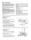
On the smooth side of the abrasive belt you will find a DIRECTIONAL ARROW\
•dl"r - n ,
ectlonal arrow. The abras ve belt must run _,
in the
direction of this arrow so that the splice does not come
apart.
1. Loosen the two abrasive belt LOCKING screws.
2. Place the abrasive belt over the pulleys with the direc-
tional arrow pointing as shown. Make sure the abra-
sivebelt iscentered on both pulleys.
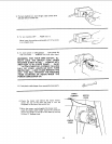
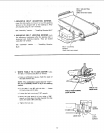
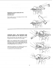
Turning the abrasive belt ADJUSTING screws will cause
the idler pulley to move in or out. When the idler pulley
is moved outward, it puts TENSION on the belt.
3. Place both of the ½" wrenches on the ADJUSTING
screws and pull the wrenches toward you. This will
stretch the abrasive belt. Move the wrenches back and
forth a few times so that you "'get the feet" of the
abrasive belt while it is stretching (TENSIONING).
/
BE LT ADJUSTING SCREWS
Apply a small amount of TENSION to the abrasive
belt by pulling the wrenches toward you, so that the
TENSION feels the same on both wrenches.
PULL WRENCHES IN THIS
DIRECTION TO APPLY
TENSION
BELT LOCKING SCREW
14