


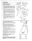
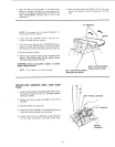
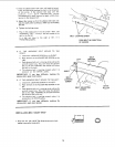

1. Assemble the two (2) End Stiffeners and the two 2
Side Stiffeners using four (4) 1/4-20 Truss head
screws. The End Stiffeners are placed On top of each
Side Stiffener as shown. Insert screws through the
9/32 inch diameter holes and finger tighten 1/4-20
nutS.
2. Attach the four (4) legs to the side and End Stiffener
using 1/4-20 screws, Iockwashers and nuts as shown.
3. Remove the four (41 Truss head screws which were
assembled in Paragraph No. One. Place the two (2
Support Channels as shown, in position align holes in
supports with holes in the Stiffeners, replace
Iockwashers and nuts, Tighten all nuts using 7/16
wrench.
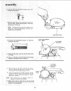
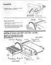
4. Assemble the motor support to steel legs with 1/4-20
screws and nuts. Motor support can be mounted to
either end of stand. Tignlen nuts
5. Install leveling feet as shown. To level Leg Set, loosen
nut on inside of leg and turn nut on outside to raise
or lower feet. Adjust alt four levelers, if necessary,
and then tighten nuts on inside of leg.
NOTE: These levelers are not intended for height
adjustment.
END STIFFENER HEX NUT
SCREW_ 1 | LOCKWASHER
S,DE ST,FFEN R
STIFFENER
SIDE STIFFENER
LOCKWASHER
\
HEX NUT _e
_ CH/%NNEL
.r
_- _ SUPPORT
_ k _.
LEG
/
SCREW
\
CHANNEL
SUPPORT
MOTOR
SUPPORT
/ NUT
LOCKWASHER
LEG
SCREW
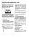
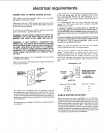
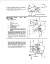
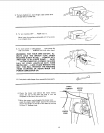
WHEN INSTALLING OR MOVING THE SANDER.
AVOID DANGEROUS ENVIRONMENT, Use the sander n a
dry, indoor place protected from rain. Keen work area well
lighted.
Place the sander so neither the user nor bystanders are
forced to stand in line with the abrasive belt or d sc.
To avoid injury from unexpected sandel movement:
= Put the sander on a firm level surface where there is plenty
of room for handling and properly supporting the
workpiece.
- Support the sander so it does not rock.
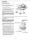
,,Bolt the sander tothe floor or work surfaceif it tends to slip,
walk. or slide during normal use.
To avoid back injury, get help or use recommended casters
when you need to move the sander. Always get help if you
need to lift the sander.
NEVER STAND ON TOOL. Serious injury could occur if the
too] tips or you accidentally hit the cutting tool, Do not store
anything above or near the toot where anyone might stand on
the tool to reach them.
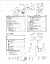
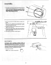
MOUNTING BELT AND DISC SANDER ON
CRAFTSMAN STEEL LEG SET.
CATALOG NO. 9-22236
NOTE: Forillustrative purposes, the Belt and Disc Sander is
shown mounted on the Craftsman Catalog No. 9-22236
Steel Leg Set. This Leg Set is included with Model No.
113.225931.
#
MOTOR MOUNT
BRACKET
THISSIDE
0 C OOc
o°o°
o o
___c oc