


CONTENTS
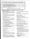
SAFETY INSTRUCTIONS FOR POWER TOOLS .............. 2
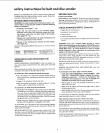
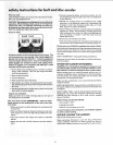
ADDITIONAL SAFETY NSTRUCTIONS FOR BELT AND
DISC SANDER ............................................................ 3
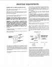
ELECTRICAL REQU REMENTS .......... 5
Check Motor Rotation .............................................. 5
UNPACKING AND CHECKING CONTENTS ...................... 6
ASSEMBLY ....................................................................... 7
Assembling Steel Legs ............................................... 8
Mounting Belt and Disc Sander on Steel Leg Set ...,.. 8
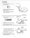
Installing Sanding Disc and Dust Trap ....................... 9
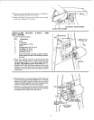
Installing Motor, V-Belt Tensioning and Tracking .... 1!
On-Off Switch ........................................................... 12
Installing Work Table ............................................... 14
Installing Abrasive Belt Tensioning and Tracking .... 14
Installing Belt Dust Trap ........................................... 15
Installing Backstop ..................................... 16
GETTING TO KNOW YOUR SANDER ............................. 16
Belt Adjusting Screws ............................................. 17
Belt Locking Screws ................................................. 17
Work Table Tilt Lock Screw ..................................... 17
Backstop Lock Screw ............................................... 18
Belt Table Locking Bolts .......................................... 18
Belt Table Stop ......................................................... 18
BASIC OPERATION ......................................................... 19
Surface Finishing on tne Abrasive Belt ................... 20
End Finishing on the Abrasive Belt .......................... 20
Finishing Curved Edges on the Abrasive Belt .......... 21
Finishing Small End Surfaces and Curved Edges
on Disc ................................................................ 21
MAINTENANCE ................................................................ 22
Motor Maintenance and Lubrication ......................... 22
LUBRICATION .................................................................. 22
Recommended Accessories .................................... 22
TROUBLESHOOTING ...................................................... 23
REPAIR PARTS ................................................................ 25
Motor Connections ................................................... 29
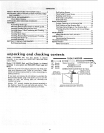
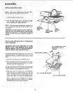
unpacking and checking
Model 113.225900 Belt and Disc Sander is shipped
complete in one carton but DOES NOT INCLUDE Steel
Legs or Motor.
Model 113.225931 Belt and 0isc Sander is shipped
complete in one carton and INCLUDES Steel Legs and
Motor.
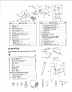
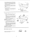
Separate all parts from packing materials and check each"
item with Ilustration and "Table of Loose Parts." Make
certain all items are accounted for, before discarding any
packing material.
contents
If any parts are m_ss_ng, do not attempt to assemble the
Belt and Disc Sander. plug in the power core. or _urn the
switch on until the missing parts are obtained aria
installed correcti V.
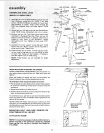
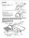
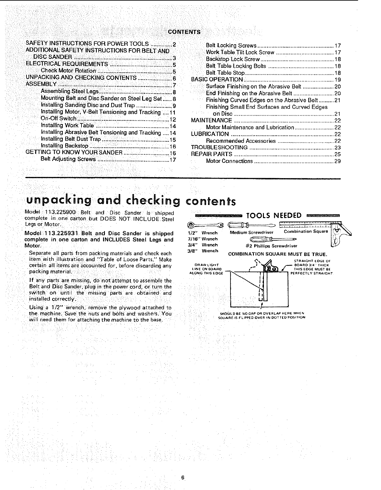
TOOLS NEEDED - - - ,
3/4"7/16"1/2"WrenchWrenChwrenchMedium_:2Screwdriver_PhilbpsScrewdrlvelC°mbinati°nSquare !i_._Square
3/8" Wrench
COMBINATION SQUARE MUST BE TRUE.
DRAW LIGHT J 8OAR° 3/4 THICK
LINE ON BOARO TNIS EDGE MUST B£
AEOf_G THIS EIE)GE I_'_ _ PERFECTLY STRAIGHT
I "N.I
[ q_u
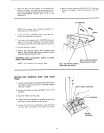
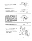
Using a 112" wrench, remove the plywood attached to
the machine. Save the nuts and bolts and washers. You SHOULD_ NOGAPOROVE,LAPNEREWHEN
Wil] need them for attaching the machine to the base SOUARES_L'PPEOOVE"_NDOTTEOPOS,T_ON
6