


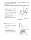

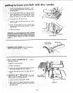

BELT ADJUSTING
SCREW
(ONE ON EACH SIDE)
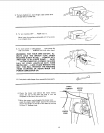
1. ABRASIVE BELT ADJUSTING SCREWS
cause the idler pulley to move in or out for applying
tension to the abrasive belt or for tracking it. They
are adjusted using the 1/2" wrenches,
See "Assembly" section... "Installing Abrasive Belt".
2. ABRASIVE BELT LOCKING SCREWS lock
the adjustment mechanism after the abrasive belt is
tensioned and tracking properly, They are locked
using the 1/2" wrench.
See "assembly" section . . . "Installing Abrasive
Belt".
BELT LOCKING
SCREW
(ONE ON EACH SIDE)
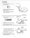
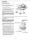
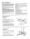
3,
WORK TABLE TILT LOCK SCREW locks
the table. It islocked using the 1/2" wrencn.
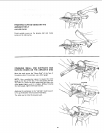
a. Using a combination square, check the angle of
the table with the disc.
NOTE: The :ombination square must be "true"--
See start of assembly section on Pg. 6 for checking
method.
b. If the table Js not 90 ° with the disc.., loosen
tilt Ic_ck screw and ti t table,
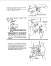
c. Loosen the lock nut using a 7/16" wrench.
d. Screw the atop screw in or out. using a 3/8""
wrench so that when the table touches the stop
screw, the table is 90° to the disc.
e. Tighten the lock nut
/
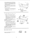
TABLE POSITIONING
LOCK SCREW
\
TABLE 1/2"
FROM DISC
LOCK NUT
STOP
SCREW
_" TILT
LOCK
SCREW
17