


18 19
18 19
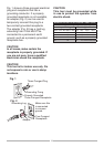
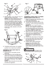
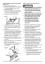
Fig. D
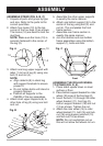
5. Repeat steps 1-4 for left rear leg (17)
and roller wheel assembly.
NOTE: The roller wheel assemblies
and bottom support bracket (18)
can be installed on either the right-
hand side or left-hand side. Always
install the roller wheel assemblies
and the bottom support bracket (18)
at the same time. The illustration
shows the roller wheels on the left-
hand side.
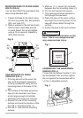
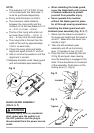
Fig. E
6. Carefully set the saw in its upright
position on a clean level surface.
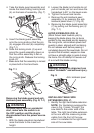
ASSEMBLE THE FOOT PAD TO
STAND (FIG. F)
1. Place all four foot pads (9) onto
each leg.
2. Place stand on level surface and
adjust so all legs are contacting the
floor and are at similar angles to the
floor, and detents in stand leg align
with support brackets, then tighten
all bolts.
NOTE: Stand should not rock after
all bolts are tightend.
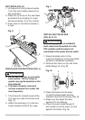
Fig. F
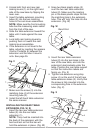
ASSEMBLE TABLE SAW TO STAND
USING LEVER LOCK (FIG. G)
1. Attach the locking lever assembly (18)
to the top of the leg (2).
2. Lift up the locking lever (19).
3. Thread the two screws (20) into the
holes (21) of the locking bracket (24)
and stand.
NOTE: You may need to loosen
the two short support brackets if the
two mounting holes are not lined up
correctly. Retighten these bolts once
you have added the lever locks.
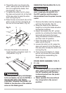
4. Attach the lock nuts (22) and tighten
with a 8 mm or adjustable wrench.
5. Install the other locking lever
assemblies in exactly the same
manner.
6. Position the saw base on the stand.
7. Line up the lever lock cover (23) to
the saw base and push down the
locking lever (19).
8. Fasten saw to stand using four
locking lever assemblies (18).
NOTE: The four locking lever
assemblies (18) are provided for
quick releasing the table saw to the
stand.
All four levers must be locked in the
down position before operating saw.
Fig. G
2
20
22
24
18
23
19
21
2
Front
18
17
9
9
12
13
14
15
16
2
11
18
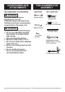
WARNING
!