


26 27
26 27
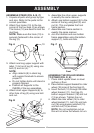
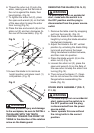
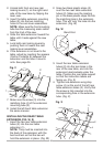
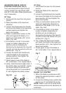
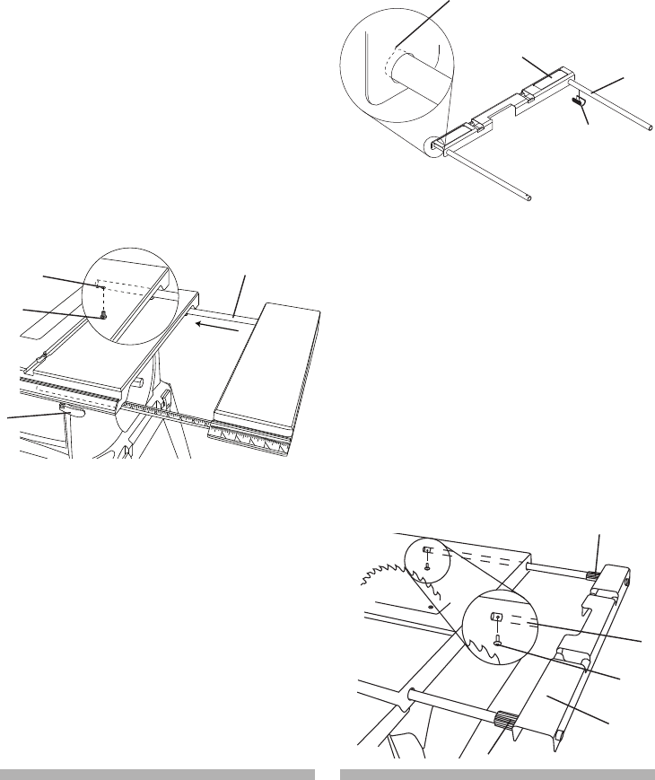
2. Unlock both front and rear cam
locking levers (1) on the right hand
side of the saw base by flipping the
lever over.
3. Insert the table extension mounting
tubes (2) into the two matching
holes in the cam lever assemblies.
NOTE: Make sure the front mounting
tube has the measuring scale visible
from the front of the saw.
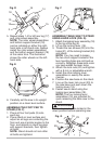
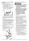
4. Slide the table extension toward the
table until it rests against the saw
table.
5. Lock both cam locking levers by
pushing them in toward the cam
locking lever assemblies.
6. If the extension is not level to the
table, adjust by
inserting the spacers
(Carton Contents S) between the
extension and the tube it mounts
onto. See page 35.
Fig. V
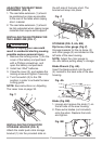
7. Make sure the screw (3) into the
matching hole (4) of the extension
mounting tube (2).
8. Install the left hand table extension
the same manner.
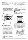
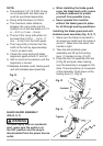
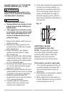
INSTALLING THE REAR TABLE
EXTENSION (FIG. W, X)
1. Insert the two rear table extension
tubes (2) into the rear table
extension (1).
NOTE: They must be inserted into
the back of the extension with the
bent end last so that the bar will
hold the extension in place. (Fig. W)
2. Snap two black plastic stops (3)
over the two rear table extension
tubes (2). Make sure the locating
pin in the black plastic stops fits into
the matching hole in the extension
tube. This will ‘lock’ the tube into the
extension. (Fig. W)
Fig. W
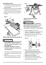
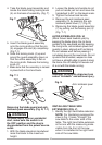
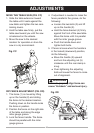
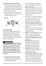
3. Insert the rear table extension
tubes (2) into the two holes in the
rear of the saw table, and into the
extension tube brackets under the
table. Position the rear table support
so that the instruction labels are
facing up. (Fig. X)
4. Tighten one extension wing stop
screw (4) on the end of the left rear
table extension tubes (2). Verify that
the screw is fully inserted into the
corresponding hole in the extension
tube. (Fig. X)
Fig. X
2
4
3
1
3
2
4
3
1
2
Bend End
3
1