


28 29
28 29
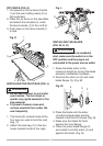
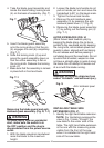
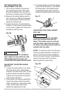
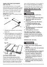
RIP FENCE INDICATOR
ADJUSTMENT (FIG. EE)
1. The rip fence indicator (6) points to
the measurement scale. The scale
shows the distance from the side of
the fence to nearest side of the blade.
2. Measure the actual distance with a
rule. If there is a difference between
the measurement and the indicator,
adjust the indicator (6).
3. Loosen the screw (7) and slide the
indicator to the correct measurement
on the scale. Tighten the screw and
remeasure with the rule.
Fig. EE
To avoid injury from an accidental
start, make sure
the switch is in the
OFF position and the plug is not
connected to the power source outlet.
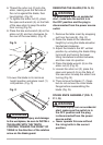
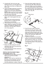
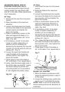
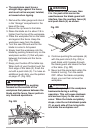
ADJUSTING THE MITER GAUGE
(FIG. FF)
1. Loosen the lock handle (1) to allow
the miter body (2) to rotate freely.
Position the miter body at 90° so the
positive detent secures its position.
Tighten the lock handle to hold the
miter body in position.
2. If the pointer (3) requires adjustment,
loosen the screw under the pointer
with a screwdriver. Adjust the pointer
to 90° on the scale, then firmly
tighten the adjustment screw.
3. To change angles on the miter gauge,
loosen the lock handle (1) and rotate
the miter body to the desired angle
as indicated by the scale. Secure in
position by tightening the lock handle.
Fig. FF
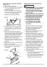
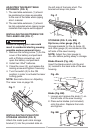
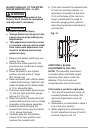
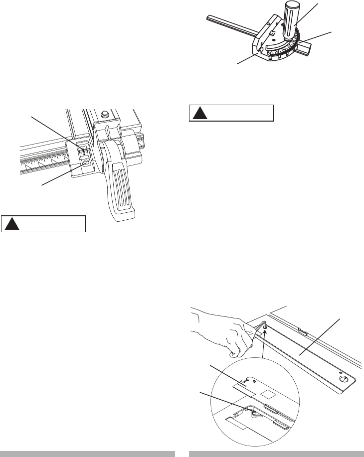
ADJUSTING THE TABLE INSERT
(FIG. GG)
To avoid serious injury, the table
insert (2) must be level with the
table. If the table insert is not flush
with the table, adjust the two bolts
(1) with a 4 mm hex wrench until it is
parallel with the table.
NOTE: To raise the insert, turn the hex
screws counterclockwise, to lower the
insert, turn the hex screws clockwise.
Do not remove the insert, adjustments
need to be made with the insert in
place to get the proper level.
Fig. GG
6
7
WARNING
!
3
1
2
WARNING
!
1
2
2