


30 31
30 31
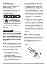
BLADE PARALLEL TO THE MITER
GAUGE GROOVE (FIG. JJ, KK)
This adjustment was made at the
factory, but it should be rechecked
and adjusted if necessary.
To prevent personal injury:
● Always disconnect plug from the
power source when making any
adjustments.
● This adjustment must be correct
or accurate cuts can not be made.
Also inaccurate adjustment can
result in kickback and serious
personal injury.
1. Remove the safety switch key and
unplug the saw.
2. Remove the blade guard for this
procedure but reinstall and realign
after adjustment.
3. Raise the blade to the highest
position and set at the 0° angle
(90° straight up).
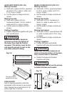
4. Select and mark, with a felt tip maker,
a blade tooth having a “right set” and
rotate the blade so the marked tooth
is 1/2 in. above the table.
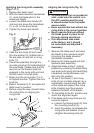
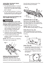
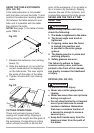
5. Place the combination square base
(1) into the right side miter gauge
groove (2). (Fig. JJ)
6. Adjust the rule so it touches the front
marked tooth and lock ruler so it holds
its position in the square assembly.
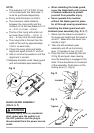
7. Rotate the blade bringing the
marked tooth to the rear and about
1/2 in. above the blade.
8. Carefully slide the combination
square to the rear until the ruler
touches the marked tooth.
9. If the ruler touches the marked tooth
at the front and rear position, no
adjustment is needed at this time.
If not or the base of the rule is no
longer parallel with the edge of
the miter gauge groove, perform
adjustment procedure described in
next section.
Fig. JJ
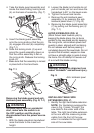
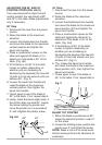
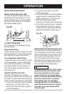
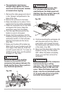
ADDITIONAL BLADE
ADJUSTMENTS (FIG. KK)
NOTE: The adjusting mechanism
is located above the blade height
adjusting hand wheel under the
tabletop. If the front and rear
measurements are not the same.
If the blade is partial to right side:
1. Turn the left adjustment screw (2)
counterclockwise and adjust the
right side adjustment screw (3)
clockwise.
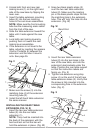
2. Remeasure, as described in steps 4
to 9 in the prior section.
3. When alignment is achieved, turn
the left adjustment screw (2) until it
touches the pivot rod (4).
WARNING
!
WARNING
!
2
1