


5
English
device that allows the compressor to run in an unloaded mode. When
the tank pressure drops to the preset
cut-in pressure, the pilot valve closes
allowing the unloading device to close
and the compressor once again
pumps into the tanks.
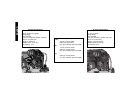
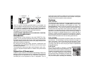
Manual Lock (for D55170 and D55180):
The manual lock allows you to manually unload the compressor with
air pressure in the tank. To operate the unloading device in the head,
rotate the flip lever to an in-line position (dashed lines). Be sure to
return lever to the loaded position after starting the engine or the pump
will not operate at preset pressures.
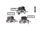
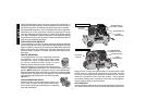
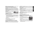
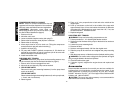
PRESSURE SWITCH
This switch (A) is used to start or stop the air
compressor. Moving the switch to the "ON"
position will provide automatic power to the
pressure switch which will allow the motor to start
when the air tank pressure is below the factory
set "cut-in" pressure. When in the "ON (AUTO)"
position, the pressure switch stops the
compressor from charging air when the air tank pressure reaches the
factory set "cut-out" pressure. For ease of starting this switch also has
a pressure release valve located on the side of the switch designed to
automatically release compressed air from the air compressor pump
head and its discharge line when the air compressor reaches "cut-out"
pressure or is shut off. Moving the switch to the "OFF" position will
open the pressure switch contacts and stop the air compressor.
SAFETY RELIEF VALVE
This valve (B) is designed to prevent system failures
by relieving pressure from the system when the
compressed air reaches a predetermined level. The
valve is preset by the manufacturer and must not be
removed or modified in any way.
AIR INTAKE FILTER
This filter (C) is designed to clean air entering the pump.
To ensure the pump continually receives a clean, cool,
and dry air supply this filter must always be clean and
filter intake must be free from obstructions.
AIR TANK DRAIN VALVES
The drain valves (D) are used to remove
moisture from the air tank after the air
compressor is shutoff.
TANK PRESSURE GAUGE
The tank pressure gauge (E) indicates air
pressure in the air tank.
REGULATED PRESSURE GAUGE
The regulated pressure gauge (F) indicates the
air pressure available at the outlet side of the
regulator. This pressure is controlled by the
regulator and is always less or equal to the air
tank pressure.
PRESSURE REGULATOR
The regulator knob (G) controls the air pressure coming from the air
tank.
Common Procedures
230 VOLT OPERATION
• Ensure that cord requirements have been met.
• Ensure that motor requirements have been met.
• Ensure that dual voltage switch is in the proper position if
so equipped.
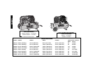
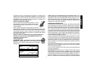
CORD REQUIREMENTS
If it is desired to operate your compressor at 230 volts it is also
necessary to replace the 115 volt plug, supplied with the motor, with a
UL/CSA listed plug suitable for 230 volts and the rated current of the
compressor as shown. A 230 volt plug as shown in the diagram can be
D
C
E
F
G
B
A