


8
English
CHECKING SAFETY RELIEF VALVE OPERATION
WARNING: Aftercooler, pump head, and surrounding parts are very
hot, do not touch. (see the Hot Surfaces identified on page 2)
1. Ensure unit is off.
2. Ensure tanks are empty by looking at tank pressure gage. Drain
tanks if necessary.
3. Grasp wire ring on safety valve.
4. Pull and release ring a few times to ensure plunger moves in and
out.
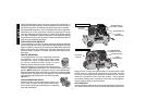
CHECKING AIR FILTER ELEMENT
WARNING: Aftercooler, pump head, and surrounding parts are very
hot, do not touch. (see the Hot Surfaces identified on page 2)
1. Ensure unit is off.
2. Allow unit to cool.
3. Unscrew filter top from filter base by turning counter clockwise
about 5 degrees.
4. Separate filter top from base.
5. Remove element from filter base.
6. If element needs cleaning, blow out with air. Replace element if
unsure.
7. Place element back in filter base.
8. Reconnect filter top to filter base and while pushing in, rotate top
clockwise 5 degrees.
STARTING UNIT
Follow the pre-start and start-up procedures in the operating procedure
section.
TURNING UNIT OFF
Follow the shut-down procedure in the operating procedures section.
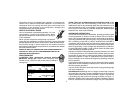
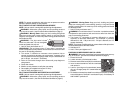
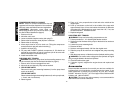
ADJUSTING REGULATOR
1. Pull regulator knob (N) out
2. Turn knob clockwise to increase regu-
lated pressure and counter clockwise to
decrease regulated pressure.
3. When desired pressure is shown on the
regulated pressure gage push knob in to
lock.
INSTALLING HOSES
WARNING: Firmly grasp hose in hand
when installing or disconnecting to prevent
hose whip.
1. Ensure regulated pressure gage reads 0 PSI.
2. Grasp hose in hand at coupler location.
3. Pull back collar on female quick connect coupler (O) located on
compressor.
4. Push male connector into female connector.
5. Release female connector
6. Grasp hose and pull to ensure couplers are seated
7. Adjust regulator to desired pressure.
DISCONNECTING HOSES
WARNING: Firmly grasp hose in hand when installing or
disconnecting to prevent hose whip.
1. Ensure regulated pressure gage reads 0 PSI.
2. Grasp hose in hand at coupler location
3. Pull back collar on female quick connect coupler located on
compressor.
4. Pull male connector out of female connector.
5. Release female connector
DRAINING TANKS
WARNING: Tanks contain high pressure air. Keep outlet of drain
away from face and other body parts. Use safety glasses when
N
O