


7
English
NOTE: For proper operation the pilot valve cut out pressure must be
below the pressure switch cut out pressure.
PILOT VALVE CUT-OUT PRESSURE ADJUSTMENT
NOTE: Unit can remain running while performing this adjustment
WARNING : Aftercooler, pump head, and surrounding parts are
very hot; do not touch. (see the Hot Surfaces identified on page 2)
WARNING - Moving Parts: Keep your hair, clothing and gloves
away from moving parts. Loose clothing, jewelry, or long hair can be
caught in moving parts. Air vents may cover moving parts and should
be avoided as well.
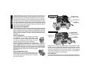
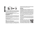
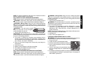
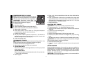
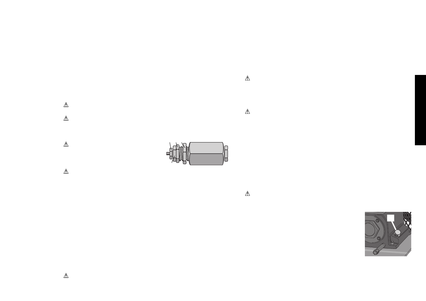
WARNING : The pilot valve is brass
which is a soft metal. Do not overtighten
screw as threads can strip out.
1. Hold “K” firmly and loosen nut “J”.
WARNING : Do not loosen screw “I” more than 1 revolution as
screw is subjected to tank pressure and can burst out which can harm
the user or surrounding personnel.
2. Turn screw “I” clockwise to increase cut-out pressure limit or
counter clockwise to decrease cut-out pressure. (example: if the
cut-out pressure on the tank gauge reads 120 psi. and desired cut
out is 130 psi, turn screw “I” clockwise)
3. Drain air from tanks through drain valves until pump begins to
charge tanks.
4. Close drain valves.
5. Monitor cut-out pressure to verify the new setting
6. Once setting is complete hold screw “H” firmly
7. Hold “K” firmly and tighten nut “J”
PILOT VALVE PRESSURE DIFFERENTIAL ADJUSTMENT
NOTE: Unit can remain running while performing this adjustment
WARNING : Aftercooler, pump head, and surrounding parts are
very hot; do not touch. (see the Hot Surfaces identified on page 2)
WARNING - Moving Parts: Keep your hair, clothing and gloves
away from moving parts. Loose clothing, jewelry, or long hair can be
caught in moving parts. Air vents may cover moving parts and should
be avoided as well.
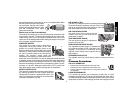
1. Hold “K” firmly and loosen nut “L”
WARNING : Do not loosen barrel “I” more than 1 revolution as barrel
is subjected to tank pressure and can burst out which can harm the
user or surrounding personnel.
2. Turn barrel “K” clockwise to increase differential or counter
clockwise to decrease differential. (for example: if pressure
differential is 100 - 130 psi and 100 - 120 psi is desired, turn “K”
counter clockwise)
NOTE : Too narrow of a differential can cause chatter of the pilot valve.
Increase differential to eliminate chatter.
3. Hold barrel “K”
4. Hold “J” firmly and tighten nut “L”
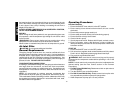
CHECKING COMPRESSOR PUMP OIL LEVEL
WARNING: Aftercooler, pump head, and surrounding parts are very
hot, do not touch. (see the Hot Surfaces identified on page 2)
1. Ensure Unit is off.
2. Locate unit onto a flat horizontal surface.
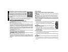
3. Remove knurled filler knob (M) from crankcase.
4. Insert a clean screwdriver into the crankcase
and remove it.
5. Look for visual signs of contaminants (water,
dirt, etc.) Change pump oil if contaminants are
present.
6. Oil should not exceed top raised line on side of crankcase (oil will be
even with bottom of threads in crankcase fill port). If necessary fill
with D
EWALT synthetic oil.
I
J
K
M
L