


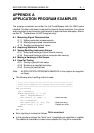

A - 4 APPLICATION PROGRAM EXAMPLES
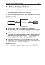
A.1.2 Making programmed measurements
In the following example the overshoot value on the rising edge of the Probe
Adjust signal is measured. This is done by programming the input conditions in
the RUN mode (INITiate:CONTinuous ON), followed by a single-shot
measurement of the peak-to-peak (PTPeak) value and the rise time overshoot
percentage (RISE:OVERshoot). The rise time overshoot value is calculated from
the rise time overshoot percentage as follows:
- Rise time overshoot =
Application summary:
•
Connect a 10:1 probe between channel 1 and the Probe Adjust signal (2000
Hz, 600 mV).
•
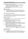
Program the following input conditions:
- AC input coupling
- Continuous trigger initiation (RUN mode).
- Trigger source channel 1.
- Trigger level zero to get a stable signal.
- Sweep time of 1 ms (100 µs/div.) to obtain two Probe Adjust signal periods
on the display.
- Peak-to-peak value of 1.6V (0.2 V/div.) to keep the positive and negative
edge on the display.
•
Stop the program to make an overshoot on the Probe Adjust signal. This can
be done by turning the screw on the head of the probe.
•
Measure and print the peak-to-peak value.
•
Measure the rise time overshoot percentage.
•
Calculate and print the rise time overshoot value.
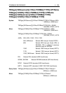
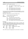
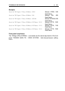
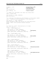
Application program:
Note: The program is supplied on floppy under file name EXAPPA12.BAS.
PTPeak
*
RISE:OVERshoot
100
V