


3 - 40 USING THE COMBISCOPE INSTRUMENTS
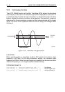
3.7.2 Input filtering
The INPut:FILTer command allows you to turn the common low-pass filter
(bandwidth limiter) on or off for all input channels at the same time. The cutoff
frequency is fixed at 20 MHz. After a
*
RST command, the filter is turned off.
PROGRAM EXAMPLE:
CALL Send(0, 8, "INPut:FILTer ON", 1) ’
Turns the filter on
CALL Send(0, 8, "INPut:FILTer:FREQuency?", 1) ’
Requests for the filter frequency
response$ = " "
CALL Receive(0, 8, response$, 256) ’
Reads the filter frequency
PRINT "Filter freq. = "; response$ ’
Prints: Filter freq. = 2.00E+07
3.7.3 Input impedance
The INPut<n>:IMPedance command allows you to specify the input impedance
low (50
Ω) or high (1 MΩ) for each input channel separately. After a
*
RST
command, the impedance of each input channel is 1 M
Ω.
PROGRAM EXAMPLE:
CALL Send(0, 8, "INPut4:IMPedance 50", 1) ’
Sets channel 4 impedance at 50
Ω
3.7.4 Input polarity
The INPut<n>:POLarity command allows you to set the polarity of the signal on
the input channel 2 and 4. The polarity can be set to NORMal (default) or INVerted
(inverted signal).
PROGRAM EXAMPLE:
CALL Send(0, 8, "INPut2:POLarity NORMal", 1) ’
Sets INV CH2 off
CALL Send(0, 8, "INPut4:POLarity INVerted", 1) ’
Sets INV CH4 on
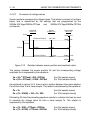
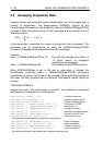
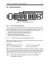
3.7.5 Vertical range and offset
The SENSe:VOLTage<n>:RANGe:PTPeak command allows you to specify the
peak-to-peak range of the signal acquisition over all 8 divisions of the display
screen for each input channel separately. From this peak-to-peak value the
vertical sensitivity per division is calculated as follows:
<vertical_sensitivity> = <peak-to-peak> / 8.
After a
*
RST command, the peak-to-peak value is set at 1.6V for channel 1, which
complies to a vertical sensitivity of 200 mV.