


3 - 50 USING THE COMBISCOPE INSTRUMENTS
TRACE POINT VALUES:
FFT trace sample values, as entered with the TRACe:DATA? query, can be
converted to FFT point value as follows:
•
Subtract from the sample value the offset value for 4 divisions:
- for 8-bit samples: 4
*
25 = 100
- for 16-bit samples: 4
*
6400 = 25600
•
Multiply the result with the following correction factor:
- for 8-bit samples: -10(dB) / -25 = 0.4
- for 16-bit samples: -10(dB) / -6400 = 0.0015625
So, the conversion from a trace sample value (Ts) to a trace point value (Ps) is
expressed by the equations:
- for 8-bit samples: Ps = (Ts - 100)
*
0.4
- for 16-bit samples: Ps = (Ts - 25600)
*
0.0015625
Note: For an explanation of Ts and Ps, refer to section 3.4.3 "Conversion of
trace data".
When relative FFT calculation is selected, the amplitude trace point values
represent the relative strength of the frequency components. The component with
the highest amplitude is taken as the reference level, referred to as the 0 dB level.
When absolute FFT calculation is selected, the amplitude trace point values depend
on the absolute reference level as selected via the CURSORS - READOUT front
panel menu, which can be one of the following:
- dBm (reference = 1 mW) with REFerence IMPedance of 50Ω
- dBm (reference = 1 mW) with REFerence IMPedance of 600Ω
-dBµV (reference = 1 µV)
- Vrms (reference = RMS signal amplitude)
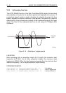
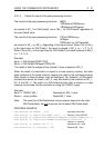
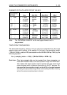
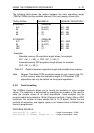
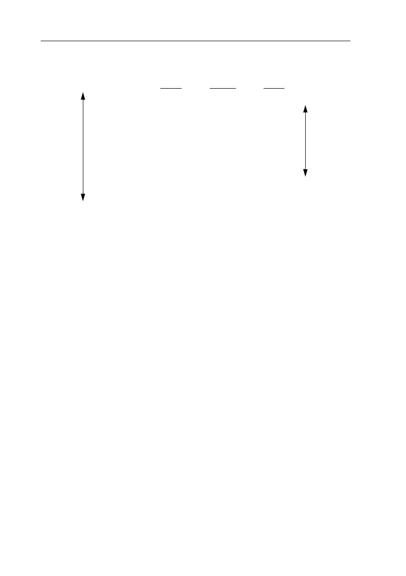
Trace sample value Trace point
8-bits
16-bits value
screen
range
top - - - - - 100 25600 - 0 dB
- - - - - - - 75 19200 - 10 dB
trace
range
- - - - - - - 50 12800 - 20 dB
- - - - - - - 25 6400 - 30 dB
mid- - - - - 0 0 - 40 dB
- - - - - - - - 25 - 6400 - 50 dB
- - - - - - - - 50 - 12800 - 60 dB
- - - - - - - - 75 - 19200 - 70 dB
bottom - - - 100 - 25600 - 80 dB
Figure 3.19 Relation between screen position and FFT value