


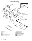
20 308–293
Service
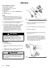
Items Needed for Service
D Gun
W
rench – provided
D
Seal Installation T
ool – provided
D
Adjustable W
rench
D
Screw Driver
D
Lubricant part no. 1
1
1–265; see
Accessories
to
order
D
Compatible Solvent
NOTE:
D
Gun Repair Kit 236–007 is available. The kit in
-
cludes the air valve assembly (14), ring packing
(22) u-cup seals (32, 33), and packing assembly
(39). See page 25 to order
.
D
The following procedure covers the replacement of
all the parts included in the Gun Repair Kit.
D
The Optional M-1265 Spray Gun (part no. 236–020
to 236–022, 236–027 and 236–028) have a two
piece needle assembly
, which includes a SST
needle shaft assembly and a SST needle tip,
instead of the one-piece needle shown in the
following instructions. See Chart 2 on page 5 for
part numbers.
WARNING
PRESSURIZED EQUIPMENT HAZARD
T
o reduce the risk of a serious injury
, follow the
Pressure Relief Procedure
on page 13 before
checking or repairing any part of the gun or sys
-
tem.
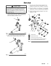
Disassembly
1.
Relieve the pressure.
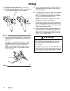
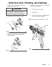
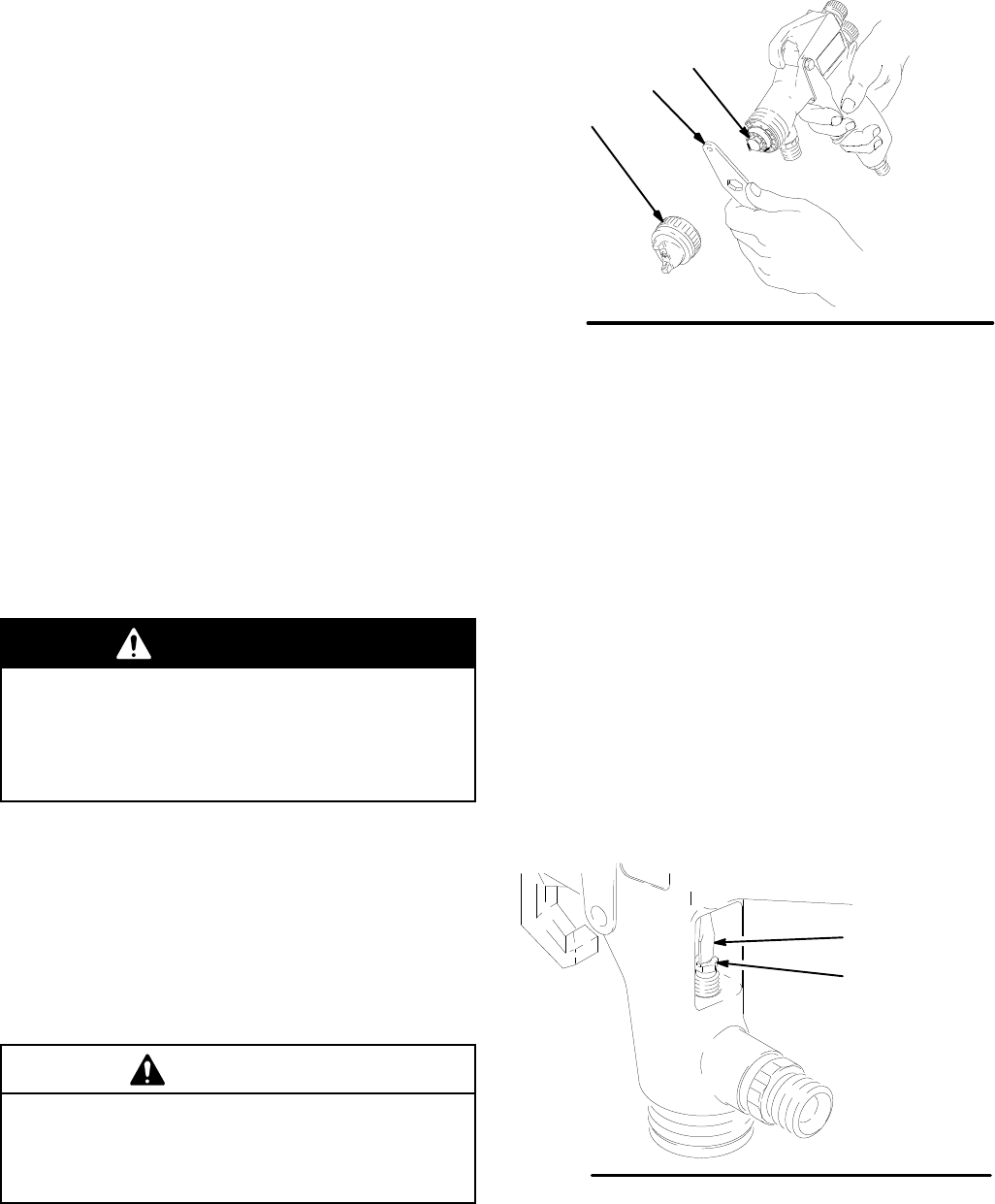
2.
Remove the air cap retaining ring (12) and air cap
(19).
3. T
rigger the gun while you remove the fluid nozzle
(20) with the gun wrench (35). See Fig. 1.
CAUTION
T
rigger the gun whenever you tighten or remove the
nozzle. This keeps the needle seat away from the
nozzle seating surface and prevents the seat from
being scratched.
Fig. 1
02060A
35
20
12, 19
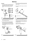
4.
Remove the fluid adjustment knob (8) and fluid
spring (16). See Fig. 5.
5.
Pull the fluid needle (21) out the back of the gun.
6.
Remove the trigger (3).
7.
Remove the fluid adjustment nut (6), spring (15),
and air valve (14).
8. T
o remove the packing adjustment screw (31),
insert a thin-blade screw driver (A) through the
back of the gun and into the packing adjustment
screw (31) as shown in Fig. 2. Be careful not to
nick or damage parts with the tool.
Fig. 2
02110
31
A