


G0644 15" Open-End Wide Belt Sander
-37-
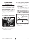
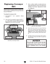
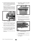
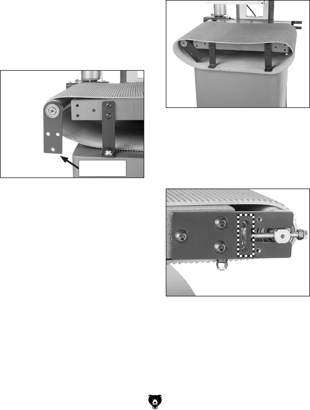
6. Use a 5mm hex wrench to remove the three
M8-1.25 x 18 button head cap screws secur
-
ing left rear conveyor roller bracket, leaving
the rear conveyor roller assembly and brack
-
et in place (see
Figure 42).
Note: After loosening the left conveyor roller
bracket, the rear conveyor roller assembly is
supported by its attachment to the conveyor
motor assembly. However, to avoid damaging
this roller assembly, DO NOT put unneces
-
sary strain on it.
Figure 42. Rear conveyor roller bracket
unattached.
Rear Conveyor
Roller Bracket
7. Loosen the four upper button head cap screws
securing the sanding assembly mounting
brackets to the conveyor (see
Figure 40).
Note: Loosening these fasteners will relieve
the strain on the brackets for the next step.
8. Use a 12mm hex wrench to remove the two
5
⁄16"-18 x 1" hex bolts, flat washers, and hex
nuts securing the left sanding assembly
mounting brackets (see
Figure 40).
Note: Reach into the cabinet stand to reach
the hex nuts.
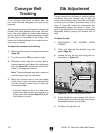
9. With assistance, carefully lift the sanding
assembly up and remove the conveyor belt,
as shown in
Figure 43.
Figure 43. Conveyor belt partially removed from
the sander.
10. Slide the new conveyor belt onto the convey-
or and re-install the parts in reverse order.
Note: Make sure the conveyor roller brackets
are mounted with the small flange facing out,
as shown in Figure 44.
Figure 44. Conveyor roller bracket flange for the
tension adjusting bolt.
11. Re-tension the conveyor belt, and adjust the
tracking (
Pages 30 & 31).
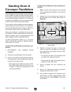
12. Re-adjust sanding drum and conveyor paral-
lelism (
Page 32).