


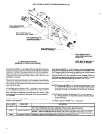
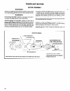

VALVE SECTION
DISASSEMBLY
To remove manifold (42432-1) remove six (6) cap screws
(Y154-57) and four (4) washers (Y14-10). NOTE: Springs
(31125) and balls (44967) are loose parts and may drop out. To
remove valve stem (40522) and spring (31125) remove pipe plug
(Y227-2-L). NOTE: Gaskets (40524 and 45459) should be re-
placed with new gaskets if manifold is removed from valve hous-
ing.
To remove valve pistons and/or components from valve housing
(40511-1); remove screws (Y132-107-C) valve plates
(40525-1) and gaskets (41222-1).
CAUTION: Exercise reasonable care when disassembling or as-
sembling valve parts, so as not to cause damage to outside diam-
eter of bushings, pistons. valves or bore diameters of bushings or
housing.
Remove end pistons (41213) using a number 8-32 machine
screw threaded into threads of piston. Pull out to remove. Tap end
of housing lightly with a soft face hammer until bushing extends
from housing enough to grasp with fingers and remove bushing
with valve stem and other piston. Remove valve stem and piston
from bushing.
Using a non-metallic rod (1/4” max. dia.), press spacer (41234)
and other bushing, valve stem and piston out opposite end of
housing. NOTE: Replace all “0” rings with new “0” rings when
reassembling.
To remove actuator and pin assembly; remove springs (39452)
move actuator to the extreme left and remove valve stem (40522)
from left side of housing. Slide actuator to extreme right and re-
move othervalve stem (40522) from that end of housing. Actuator
and pin assembly can now be removed from housing. To remove
trip tabs; remove retaining ring (Y145-18) from actuator, loosen
screw (45457) and slide trip tab off actuator.
To remove screen (41266) remove screws (Y8-243-C) and plate
(41246-1).
REASSEMBLY
It is recommended “0” rings be replaced with new “0” rings when
reassembling. Lubricate all “0” rings with 36460 lubricant and
coat pistons and valve stems with 29665 spindle oil when assem-
bling.
Assemble valve stem (40522) with “0” ring (Y325-7) and spring
(31125) to manifold and secure with pipe plug (Y227-2-L). As-
semble balls (44967) and springs (31125) to manifold. Assemble
“0” rings (Y325-14) to manifold.
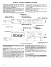
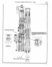
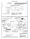
Assemble “0” rings (Y325-17) to spacer (41234) and assemble
to housing with large hole in spacer facing towards front end of
housing (see cross section below).
Assemble “0” rings (40284 and Y325-17) to bushings (41214-1
and 41215). Assemble “0” rings (Y325-15) to pistons (41213).
Assemble “0” rings (15066) to valve (41217-1).
Assemble valve (41217-1) and pistons (41213) to bushing
(41214-1) and assemble bushing to housing. NOTE: See cross
section view below for correct installed position of bushing, piston
and valve stem.
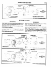
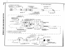
Assemble valve stem (41216) and pistons (41213) to bushing
(41215) and assemble bushing to housing, NOTE: Align slots in
bushing with exhaust holes in housing as shown in auxiliary view
on page 11. Assemble pistons as shown in cross section view be-
low.
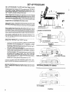
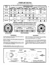
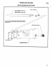
Assemble trip tabs (40523-1), with spacers (41572), to actuator
(see correct assembled position below) and secure with screws
(45457). Assemble retaining rings (Y 145-18) to actuator. Position
actuator in housing and assemble valves (40522) with “0” rings
(Y325-7) to housing and pins of actuator, securing actuator in
housing.
WRONG
RIGHT
BOTTOM VIEW OF TRIP TABS SHOWING
CORRECT ASSEMBLED POSITION.
Assemble springs (39452) gaskets (41222-1) spacer (46496)
and valve plates (40525-1) to housing and secure with screws
(Y132-1074). NOTE: Torque screws to 45 - 55 in. Ibs.
When assembling the valve section to tool, be sure bracket
(41235) page 17, is positioned between the two trip tabs and air
tubes are properly aligned. Secure valve section to spindle hous-
ing with cap screws (Y 154-54) and washers (Y14-10).
CROSS SECTION THRU VALVES
ASSEMBLE PISTONS WITH THREADED
HOLE POSITIONED AS SHOWN
ASSEMBLE WITH
HOLE AS SHOWN
LARGE
10