


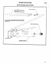
ACCESSORIES
M104
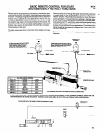
DUAL SPINDLE SECTION
32
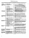
DISASSEMBLY
REASSEMBLY
The dual spindle attachment can be serviced without removing
the complete assembly from the tool. Using the 4 mm hex wrench
supplied with the unit, loosen both adjusting screws (45992) -
NOTE: Alternately unthread adjusting screws approximately 1/2
turn at a time or unthread screws simultaneously to prevent dam-
aging the unit.
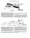
Pack bearings and coat gears with a good grade of bearing
grease when assembling. Saturate oil reservoirs with a good mul-
tigrade 10W/30 oil.
After the body and components have been removed from the
adapter, driving spindle (47757-302) and components can be re-
moved from adapter. To remove bearing (32325) and/or gear
(45991); remove retaining ring (45989), press bearing back on
spindle to expose needle roller (45986) and remove roller to re-
move gear. Remove bearing from spindle.
Insert a dummy adjusting screw (45992) (or a shaft of the same
diameter) thru adapter side of body to maintain alignment of parts
to be assembled into body and assemble nylon washer (45994) to
dummy screw. Assemble one bearing (46002), spacer (46995)
and another bearing (46002) into gear (45996) and assemble
gear to the dummy screw. Assemble nylon washer (45993) into
body, bending washer slightly to insert into body, and assemble oil
reservoir (46009) into body.
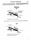
To remove gear (45996) and/or components, remove crescent
ring (45997). Rotate spindle turret, and at the same time, pull back
slightly on turret to locate alignment of spindle with notch in body
(45999) and remove spindle assembly from body. To remove gear
(45996) from body, remove oil reservoir (46009) and nylon wash-
er (45993) bending washer slightly to remove. Bearings (46602),
spacer (45995) and washer (45994) are loose parts and will drop
out. Do not disassemble spindle (46022). If necessary to replace
a part, replace as complete spindle assembly (46022).
Assemble adjusting screw to spindle assembly (46022) and as-
semble nylon washer (45994) to adjusting screw. Assemble the
spindle assembly into body while holding adjusting screw in align-
ment with dummy screw to maintain pans alignment and using
adjustment screw to push the dummy screw out of body. NOTE:
Align spindle assembly with notch in body to assemble. After as-
sembling spindle to body, assemble crescent ring (45997) to ad-
justing screw, securing screw to body.
Reassemble driving spindle (47757-302) and components and
the body (45999) and spindle assemblies (46022) to adapter
(47757-298) in the reverse manner of disassembly.
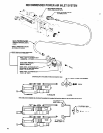
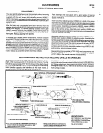
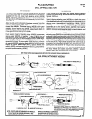
RECOMMENDED METHOD FOR HOLDING DRILLS IN SPINDLES
To properly hold drill bit in Collet and reduce the chance of slip-
page, a flat must be ground on the shank end of the bit. The flat
Insert bit into spindle and into locking insert (where applicable) in-
should be approximately 5/16” (8 mm) long and the depth should
suring that one of the set screws locates squarely on the flat of the
be 1/3 of the bit diameter. NOTE: If bit is too large to fit into locking
bit. Tighten Collet firmly, then tighten set screws. NOTE: DO NOT
insert (smaller capacity dual spindles do not have insert), a
overtighten Collet. NOTE: Intent of set screws is only to keep bit
square must be around onto the shank end of the bit.
from turning in Collet.
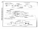
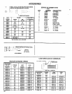
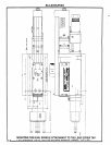
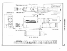
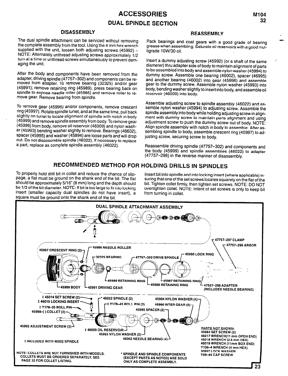
DUAL SPINDLE ATTACHMANT ASSEMBLY
45986 NEEDLE ROLLER
47757-297 CLAMP
47757-296
ARBOR
989 RETAINING
RING
45980
45991 DRIVING GEAR
RETAINING
RING
47557-290 ADAPTER
(INCLUDES NEEDLE BEARING)
-
l
46022 SPINDLE (2)
45994 NYLON WAS
Y178-45 ROLL PIN (2) 45996 INTER GEAR (
45995 SPACER (2)
$46014 SET SCREW (2)
$46015 LOCKING INSERT
$ Y176-35 ROLL
45998-( ) COLLET (2)
45992 ADJUSTMENTS
$46009 OIL RESERVOIR
PARTS NOT SHOWN:
45993 NYLON WASHER (2)
45984 SET SCREW (2)
46017 WRENCH(11 mm OPEN END)
$ INCLUDED WITH 46002 SPINDLE
46002 NEEDLE BEARING (4)
46018 WRENCH (2.5 mm HEX)
46019 WRENCH (11mm BOX END)
Y106-4 WRENCH (4 mm HEX)
NOTE: COLLETS ARE NOT FURNISHED WITH MODELS.
l
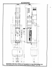
SPINDLE AND SPINDLE COMPONENTS
30997 LOCK WASHER
Y99-44 CAP SCREW
CoLLETs MUST
BE ORDERED SEPARATELY. SEE
PAGE 32 FOR COLLET LISTING.
(EXCEPT PARTS AS NOTED) ARE SOLD
ONLY AS COMPLETE ASSEMBLY.
23