


SET-UP PROCEDURE
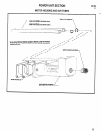
SET-UP PROCEDURE: The ARO Lead Screw Tapper is adapt-
able to many applications. Its maximum stroke of 2” can be re-
duced to a minimum stroke of 3/16” by adjusting the “RETRACT’
and “STOP” trip tabs, located beneath the nameplate door. Any
stroke setting of less than 2” can be positioned at any point within
the 2” length by properly setting the trip tabs.
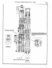
When shipped from the factory, the spindle is in its full retracted
position with the internal sleeve bracket addressing the “STOP”
trip tab and the inside edge of the trip tab directly under the zero (0)
index line on the gauge plate (step 1). The unit is thus properly cal-
ibrated forstroke indication. In this position, the unit should remain
stopped when air is admitted to the main air inlet.
IMPORTANT NOTE: Adjustment of the trip tabs should be made
BEFORE connecting air pressure to the tool or with the air supply
line to the tool shut off and exhausted (drained) of compressed air.
Prior to setting the stop trip tab, the spindle will have to be ad-
vanced at least 1/4” in order to allow moving the stop tab to the left
(trip bracket 41235 must be moved away from trip tab). To accom-
plish this, rotate chuck until trip bracket has moved sufficiently for-
ward to allow the stop trip tab to be moved to the desired position.
The purpose of setting the stop trip is to prevent excessive “cut-
ting of air” during the advance cycle, decreasing cycle time and
increasing production.
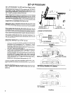
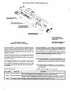
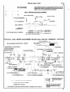
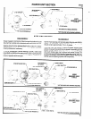
The following example of set-up (figure 1) is given to explain the
setting of the “RETRACT” and “STOP” trip tabs.
1.
Determine the distance between the tap and the desired tap
penetration into the workpiece (3/4” in illustration). Loosen
set screw in retract trip tab one (1) turn and slide tab so the
inside edge of the tab is aligned with the 3/4” mark on the in-
dex scale. Tighten set screw (step 1).
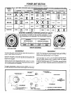
2.
To determine the distance necessary to retract the tap to suf-
ficiently clear the workpiece (9/16” in illustration), subtract a
constant of 1/16” from the 9/16” (9/16” - 1/16” = 1/2”). Sub-
tract the remainder (1/2”) from the previously set desired tap
penetration (3/4”) to yield 1/4” (3/4” - 1/2” = 1/4”). Loosen set
screw one turn in stop trip tab and slide tab so the inside edge
of tab is aligned with the 1/4” mark on the index scale (step 2).
Subtraction of the constant 1/16” is necessary to allow for the
spindle over-running the set stop position by l/l 6”.
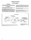
Once set, the depth control will consistently repeat within .005”,
assuming stable air pressure is maintained (90 p.s.i.g.) at the air
inlet.
BEFORE STARTING tool, be sure pitch of tap and lead screw
match. Thread pitch is etched on both the lead screw and lead
screw nut.
RETRACT TAB-’
ACTUATOR 40521-1
L
STOP TAB
TRIP BRACKET 41235
DESIRED TAP PENETRATION
1/16 CLEARANCE
TOTAL DESIRED RETRACT LENGTH
FIGURE 1
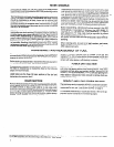
(PUSH LEFT TO RETRACT)
TAB
(PUSH RIGHT TO STOP)
POSITION OF TRIP TABS AFTER UNIT HAS BEEN ADVANCED
AND STOPPED, SHOWING 1/16” OVERRIDE
STEP 2
POSITION OF TRIP TABS AFTER COMPLETE CYCLE AND WITH
1/16” OVERRIDE
FIGURE 2